Tests of homemade 200,000 volt capacitors
Copyright 2012 Brian Fraser
Last modified 9-10-15q
Links:

This is an "educational toy " Van de Graaff generator from Edmund Scientific that my parents bought for me over 50 years ago. It still runs fine with all the original parts (including the belt). It is advertised as producing 200,000 volts at a few microamperes. It is safe when used as directed in the user manual. Here, however, it is used to test Leyden jars and capacitors. These devices accumulate (store) the output of this machine for 2 to 4 minutes. The accumulated charge can be lethal. Such a setup is not safe for use by children or testosterone crazed males trying to impress their girl friends, or by people who have no experience with high voltage techniques. It can also damage nearby voltage sensitive electronic devices like computers, laptops, TV remotes, ipads, and so forth.* Hence, this page is about test results and NOT about how to operate the various setups shown here. (* but don't jump to conclusions. I thought I fried a TV remote during one of my experiments. But it turned out someone inadvertently deprogrammed the unit by holding a button down too long. It functioned fine when reprogrammed.)
The second picture shows the placement of a spark gap electrode. It is used to prevent overvoltage on the device being tested.
These are two large Leyden jars constructed from a plastic trashcan and a discarded cheese ball jar. Each could only be charged for about 2 minutes. A charge of 4 minutes caused dielectric failure ("punch through") accompanied by a loud firecracker-like explosion. They could stay charged for at least several minutes after the generator was shut off. Note that the foil does not go all the way to the top of the containers. This generous gap is necessary to prevent flashover.
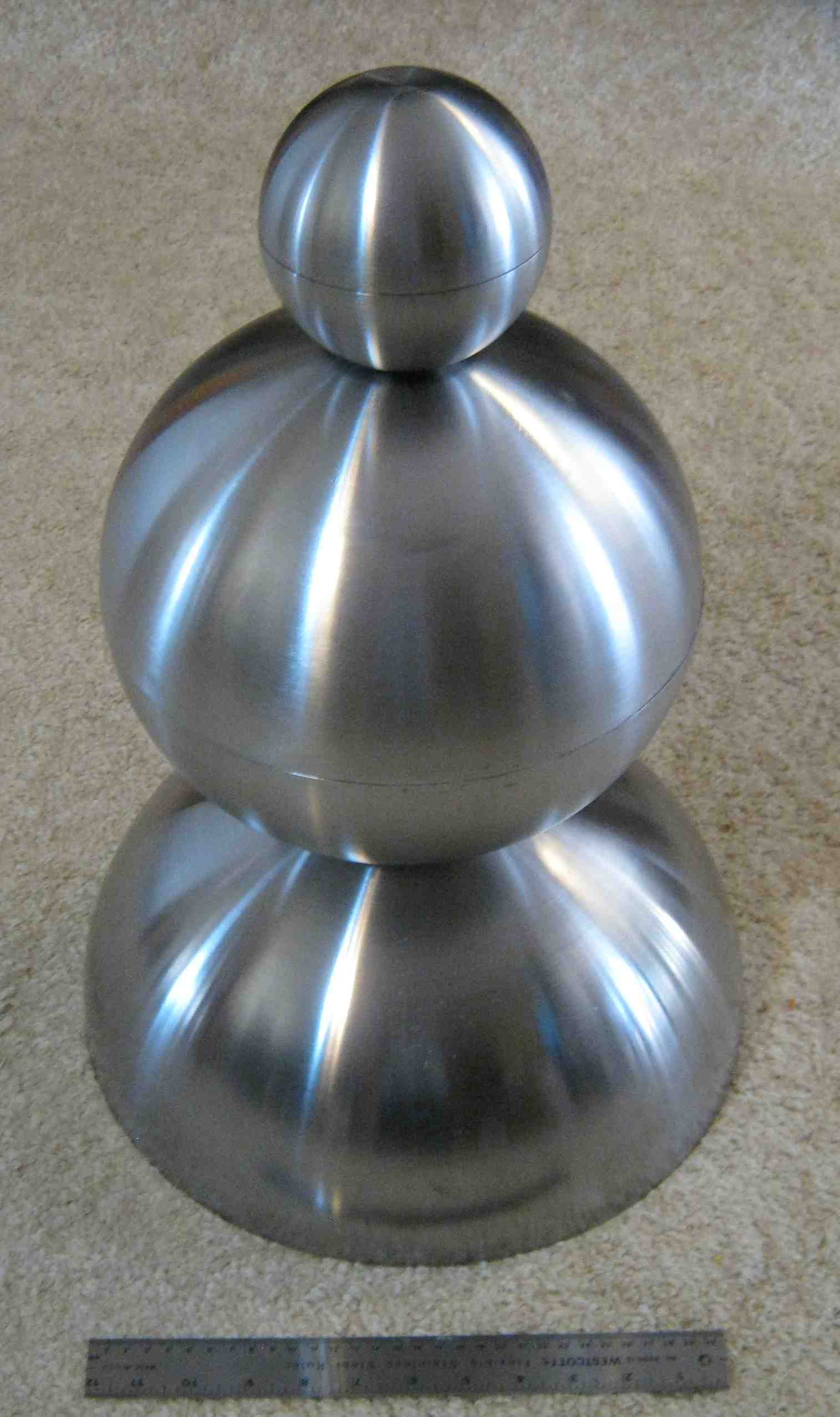
This is a discharge wand with a 2 foot PVC handle. It is made from 1/4" steel rod and two Baoding balls (finger exercise balls) that I got at an oriental food store. I drilled and tapped the balls for the rod. A bolt with two flat washers and two split lock washers (for tension) allows the spherical tips to be adjusted as required. The bolt goes through an eye screw which is epoxied into the handle. During use, one ball is touched to the generator ground and the other is brought near the high voltage terminal. When connected to a Leyden jar, the high voltage terminal discharges with a very loud, thick, bright, long spark.

This shows dielectric breakdown ("punch through") at the bottom of the trash can and at the side of cheese ball container. Ordinary aluminum foil was used in the construction. Breakdown punches a neat pinhole in the plastic and blows back the foil. These holes were later plugged with Silicone I sealant, and normal operation was restored.

This shows the placement of foil (aluminum flashing) on a tube-within-a-tube PVC pipe capacitor. Normally a tube capacitor could be constructed with one tube, with foil on the inside and foil on the outside. But this one was intended to use distilled water as the dielectric. The water will go into the annulus formed when the 1.5 inch pipe is placed inside the 2 inch pipe. Note that thin wall PVC pipe was used in this case.
This shows arc-over tracks from surface corona discharge. The aluminum flashing electrodes had to be cut back about 4 inches (both inside and outside) to prevent flashover in air at 200,000 volts. The dielectric stress at the ends of the foil is very high and could be reduced by using Rogowski profiles at foil ends. Lacking that, even corona rings would help. Another alternative is to use semiconductive tapes or coatings containing zinc oxide, silicon carbide, blotting paper treated with copper sulfate, "corona dope", etc. Corona and arc-over eventually destroy capacitors, and also interfere with charging.
High voltage end of the capacitor tube. The outer foil (aluminum flashing) is at ground potential. The inner electrode connector is a stainless steel scouring pad epoxied to a bamboo stick and is threaded with #16 AWG wire. It connects with the innermost cylindrical electrode of aluminum flashing. The distilled water goes into the annulus between the two pipes. The epoxy coated paper centering ring is used during dry testing and construction. The thick insulation on the high voltage wire is made from three different diameters of vinyl tubing, the smaller ones being pulled through the larger ones. This capacitor is being dry tested for flashover (at 200,000 volts) and charging time characterization. It can store a dangerous amount of energy even with air/PVC as the dielectric.
This shows the scheme for sealing the inner pipe within the outer pipe and the passthrough for the water fill tubes. The brown rings are made from epoxy coated Kraft wrapping paper. The large ones are cemented to the pipe with expoy (the 6 minute kind) and the narrow ones are movable. The water fill tube is pressed against the capacitor tube with tape and then epoxied. The tape is later removed. The helical wrapping of the water tube keeps the inner dielectric pipe centered within the outer pipe. For final sealing, the inner dielectric pipe assembly is slid into the outer dielectric pipe. The inner pipe is then moved right or left a few inches so that a 1/2" wide layer of Silicone I sealant can be applied first to one end and then to the other. With the ends of both pipes flush, the narrow rings are pushed into the annulus with a suitable tool to compress the sealant and fill any gaps. The water fill tubes are stowed by coiling them in the air gap of the annulus.
This shows the completed capacitor. The outer foil (aluminum flashing) and the two copper drain wires are covered with a couple of layers of packaging tape.
The following test results are typical:
PVC Capacitor tube charging test (dry)
Tube: 3’ x 2” double wall coaxial PVC thin wall water pipe (1.5” + 2”)
Conditions: SG = 43 mm; RH 30%; dry capacitor, horizontal
Generator: 200,000 volt @ 5 microamp (nominal) Van de Graaff
Date: July 6, 2001
Time at Spark Gap firing
Difference (seconds)
25:35
42
26:17
39
26:56
39
27:35
39
28:14
38
28:52
37
29:29
36
30:05
Note that the charging time shortens somewhat as the test proceeds. This is probably because the dielectric tends to polarize over time. A single spark does not fully discharge it. This leaves less dielectric that is actually polarizable, and so the charging times decrease. At the end of the test, the capacitor can carry a residual charge even after being discharged with a wand several times. In fact, during early testing, I took this capacitor completely apart, handled all the parts and pieces, let them set overnight on the work bench, and when I reassembled it a day later, I got a mild shock. The lesson: Never trust a "fully discharged" capacitor! (the "recharge" comes from further relaxation of the polarization of the dielectric as well as from electrons that have diffused into the dielectric itself migrating back out. For the latter, see http://205.243.100.155/frames/lichtenbergs.html For more on the "electret effect" see https://sites.google.com/site/appliedbiophysicsresearch/electrets ; http://en.wikipedia.org/wiki/Electret )
The tests for the capacitor in the vertical position gave the same results as those for the horizontal..
Rough measurements using a 28" length of active plate section gave a calculated annular volume of 175 ml. I then injected 90 ml of "distilled" bottled water (grocery store grade). I found unexpectedly that 90 ml was actually the full capacity. I sealed the tubes and proceeded with another charging test:
PVC Capacitor tube charging test (wet)
Tube: 3’ x 2” double wall coaxial PVC thin wall water pipe (1.5” + 2”)
Conditions: SG = 43 mm; RH 30%; wet capacitor, vertical
Generator: 200,000 volt @ 5 microamp (nominal) Van de Graaff
Date: July 7, 2001
Time at Spark Gap firing
Difference (seconds)
34:03
49
34:52
48
35:40
46
36:26
45
37:11
44
37:55
44
38:39
44
39:23
44 40:07 41 40:48 44 41:32 46 42:18 46 43:04
The results were both encouraging and disappointing. The charging time increased by 8 seconds, indicating higher capacitance, as expected. But the increase was disappointingly small. Still, this was my first experience with a water capacitor. The fact that it has any capacitance after the water was added was encouraging. The device did not leak either, nor flash over, which means that the construction methods are valid, at least for the stated spark gap setting.
In subsequent tests, a Spark Gap setting of 62 mm gave a charging time of 65 seconds, and an SG setting of 70 mm gave about 78 seconds. In the latter case, corona losses at the generator were becoming significant and caused some scatter in the data. A 2.75 inch Spark Gap appears to be roughly the limit of this set up. If the dielectric strength of air is taken as 3 kV/mm, that works out to be about 210 kV. (http://en.wikipedia.org/wiki/Dielectric_strength ) A current of 5 microamps for 70 seconds transfers 350 microcoulombs of charge. Energy stored in a capacitor is U = 1/2 QV . At 200,000 volts that represents about 35 joules (or enough energy to light a 20 watt fluorescent light bulb for almost 2 seconds). However, that figure is probably high because a Fluke 115 meter shows that the capacitance is less than one nanofarad (which, with U = 1/2 CV2 , would be equivalent to 20 joules; additionally this generator's output is probably more realistically 1-2 microamps).
Water, as a liquid dielectric, has the advantage of picosecond relaxation times, which allows for very fast rise times (tens of nanoseconds) in properly constructed high voltage pulse generators (ones that use triggered spark gaps, transmission line techniques, reduction of inductive loop areas, etc.; fast rise times are believed to improve performance in antigravity generators.) Water has a relatively high dielectric constant of about 78.3. A major limitation though is that distilled water tends to be very corrosive. It tries to dissolve just about anything (even air), and becomes somewhat conducting as a result. The residual conductance results in self-discharge, and therefore limits the time available for extracting stored energy after charging. My implementation has no provision for continuous deionization of the water, and this is undoubtedly a limitation. However, the water is in an insulated annulus. But even so, it will still act as a slightly self-discharging capacitor. (For pulsed switching see: http://event.cwi.nl/icpig05/cd/D:/pdf/18-221.pdf ; http://www.pulsedpwr.com/PDFs/PPLabsInc-HPMPhaseII-PPPS2009Paper.pdf ; http://alexandria.tue.nl/extra2/200712432.pdf )
Other dielectrics could be used of course. Transformer oil (or an ultradry mineral oil) has a dielectric constant of 2 or 3 and is conventionally used in capacitors, and will work at high voltages. Organic conjugated dienes have dielectric constants in the tens of thousands, but saturate quickly when charged with only a couple of volts ( http://www.springerlink.com/content/m117200kq47q1n10/ ; http://www.patentstorm.us/patents/6544651.html ; http://opus.kobv.de/ubp/volltexte/2011/5119/pdf/stoyanov_diss.pdf ). Certain polar organic liquids, with a k in the range of 30-200 can work too. Propylene carbonate, for instance, is especially effective as a capacitor dielectric, as is dimethlyl sulfoxide. Use of these (and others) as a dielectric can give energy densities 2 or 3 times that of a water capacitor, but without the problems associated with water. See US patent 3903460 and 3558908 for more information. Lead magnesium niobate has a k around 10,000 ( http://physics.info/dielectrics/ ), calcium copper titanate, 250,000 ( http://en.wikipedia.org/wiki/Relative_permittivity ; http://www.paper.edu.cn/index.php/default/scholar/downpaper/dangzhimin511435-201001-20[1].pdf ). There are even more exotic materials that have "giant dielectric permittivity" with a k in excess of a billion! ( http://repository.upenn.edu/cgi/viewcontent.cgi?article=1158&context=physics_papers ) See also dessicants)
In retrospect, I should have tried filling the water capacitor with a mineral oil / barium titanate suspension. This would largely stop the self-discharge. (In May 2012 I dried out the capacitor and injected it with about 90 ml of barium titanate suspension. Testing with a 43 mm spark gap gave a charging time of 68 to 71 seconds, compared with 42 to 36 seconds for the original dry capacitor. Oddly, the charging time seemed to increase slightly with time during the testing. Because of the crude experimental conditions, and the fact that 10 months had elapsed since the first tests, I would only conclude that addition of the suspension gave some improvement in capacity, and that it was probably better than water in this DC application.)
But my thinking here is obviously skewed to DC applications. One of the best ways to use water capacitors is in pulsed power applications:
"Water is a rather important dielectric liquid in pulsed-power applications. It has a relatively high electric breakdown strength (up to 3 x 10⁷ V/m) for submicrosecond electric stress and, owing to its high permittivity, can store quite large energy densities for short times. Most of the electrical characteristics of organic dielectric liquid insulators . . . are also valid for water.
A small fraction (10-7) of water molecules is always dissociated into H+ and OH-. These ions lead to a residual conductivity of 4 x 10⁻⁶ S/m even for very clean water. Therefore water is inadequate for DC-insulation. . . . Nevertheless, ionic currents do not contribute to the initiation of breakdown for submicrosecond pulses. This has been demonstrated even for salt solutions with concentrations up to 1M. . . . Water, which is largely used in short-pulse applications, has, in addition, the benefit of a high dielectric constant (e= 81), which allows one to store high energy densities.
Under short-duration electric stress, the electric strength of water becomes comparable to that of other liquid insulators. At 1 ms, its strength is around 40MV/m. . . . Its self-discharge time constant is . . . 180 ms. In contact with air, the conductivity increases up to s = 10-4 S/m owing to dissolution of CO2, leading to . . . 7.3 ms Therefore energy can be stored only for a rather short time in water-insulated systems, determined by the shorter of the two time constants for breakdown . . . and self-discharge." (Pulsed Power Systems Principles and Applications, Hansjoachim Bluhm (2006) p. 38,40; Note: conductivity is given in Siemens per meter)
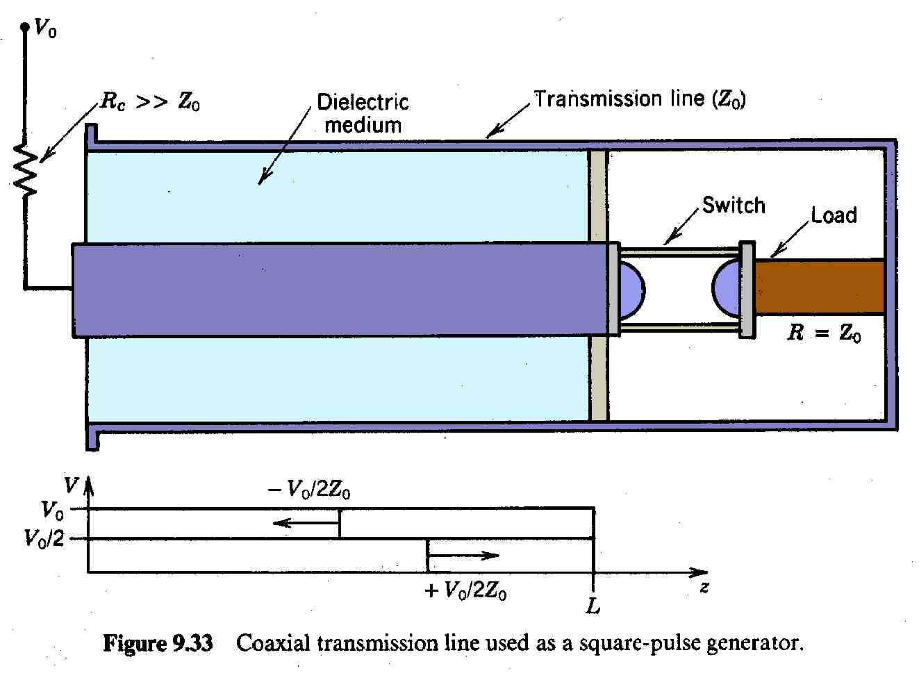
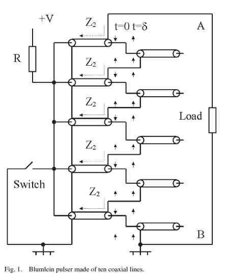
A water capacitor is best used as an intermediate energy store for pulses in the sub-microsecond range. For example, a single tube version of the PVC capacitor (above) could be built, and five of them connected in a Marx generator configuration. Charging the Marx generator with a toy van de Graaff generator will take several minutes but the final output spark could be about a million volts delivered over a few microseconds. As in typical pulsed power configurations, the output could then be fed into a water capacitor which can be charged quickly as an intermediate energy store, and then discharged quickly through another spark gap. The fast relaxation time of the water molecule gives an even faster output pulse (tens of nanoseconds?) which is then fed into pulse forming and impedance matching networks before coupling to the load. Here is a representative illustration from Kumamoto University:
Credit: http://pps.coe.kumamoto-u.ac.jp/streaming/PulsedPower/generator/content2.htm
See also: http://www.sandia.gov/pulsedpower/prog_cap/pub_papers/Z_MITLs_120401.pdf
http://www.sandia.gov/pulsedpower/newsreleases/reports/Pulsed_PWR_1st_40yrs.pdfOther schemes use a peaking capacitor. The Marx generator, with its long chain of spark gaps and simply its overall size, has a fairly high inductance (a few microheneries ), which is difficult to reduce because of the extremely high voltage gradients. A properly constructed peaking capacitor, along with another spark gap switch, can reduce this to a few nanoheneries, which in turn enables rise times of only a few nanoseconds. Some applications, such as flash radiography of exploding materials (as in atomic weapons research), require these high power, ultrashort pulses.
Pulsed power (in the terawatt to exawatt range) has a lot of important applications. See Links below. But those are advanced topics. For now, let's continue with simple DC capacitors. Here is a capacitor I tried to make with barium titanate:
Barium titanate is another common high k material (k of 1250–10,000). I tried making a high voltage capacitor by using it, paraffin wax, computer printer paper, and four copper foil plates. It was a complete failure. I could not even get it to charge. Apparently, there was some sort of internal leakage, but I did not have a gigohm meter (examples) handy to investigate. At 200,000 volts even a megohm is considered very conducting (do the math). A good insulator would be above 10 teraohms at a minimum. In the photo of the disassembled capacitor shown at right, the two copper plates are separated by a stack of fused waxed paper about 6 mm thick. Notice the extra border needed when tabs are brought out. The resistance could not be measured with a Fluke 115, and so it is greater than 40 megohms (as measured with low voltage).
Years later I decided I wanted a more reliable capacitor and came up with a design that uses three PVC pipes and resistive grading for corona control.:The details are in proposed_500kV_cap.pdf
Brown's lead plate capacitor


A stack of lead plates, paper index cards, and paraffin wax was to be used in a test of Brown's massive cellular gravitator. But because of the previous failure with paper and paraffin, the experiment was postponed indefinitely. However, Brown has suggested that a slightly conducting ("semiconducting") dielectric in this kind of application might have an advantage over a perfectly insulating one.

This is a tubular asymmetric capacitor similar to one described in Brown's patents. It is suspended from two pink nylon strings. The inner tube is filled with white barium titanate and bees wax. The outer one is filled with paraffin. The outside is wrapped with aluminum foil and serves as the negative electrode. The wire down the center is in contact, asymmetrically, with the barium titanate/wax mixture. Upon application of a 100,000 volt DC pulse, the assembly is expected to move in the direction of the ruler.
Compare this with Naudin's Poynting Flow Thruster (PFT, http://jnaudin.free.fr/html/pft01.htm ) His remarks on this are similar to mine .
Links-General:
http://en.wikipedia.org/wiki/Electrostatic_generator"Van de Graaff Generator", A. J. Martins , H. M. Pinto http://www.clab.edc.uoc.gr/2nd/pdf/36.pdf
"The Van de Graaff Generator", Trump, Merrill & Safford (1938). http://lateralscience.co.uk/VDG/VDG.html This machine outputs a "half a million volts at around 200uA". (That is sort of equivalent to 100 watts because the 200uA is continuous short circuit amps. If you plan on doing antigravity replication experiments, you will want a VDG in this volt-ampere range. Additional spark gap switches and pulse forming are needed to get the impulse power levels up to a modest 10 million watts (preferrably higher) with a repetition rate of 10 pulses per second (preferrably higher). I am trying to design one in this range that should be somewhat easier to build. See ProjectWhitefire )
See also: "The Electrostatic Production of High Voltage for Nuclear Investigations", R. J. Van de Graaf1, K. T. Compton, L. C. Van Atta, Rhys. Rev., vol. 43, 149 1933 http://www.fisicateorica.me/repositorio/howto/artigoshistoricosordemcronologica/1933
%20VAN%20DE%20GRAAFF%201933%20Invention%20of%20electrostatic%20accelerators.pdf
http://mark.rehorst.com/Van_de_Graaff/ (construction experiences)
http://www.physicsplayground.com/VDG%20Instructions/HOW%20TO%20MAKE%20A%20VDG%202012.pdf (very good!)
http://amasci.com/emotor/vdgbug.html (Van de Graaff Generator Debugging )
http://en.wikipedia.org/wiki/Triboelectric_effect (triboelectric series)
http://members.tm.net/lapointe/Main.html ("Bob's High Voltage Home Page")
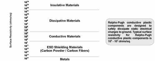
http://distributionbizwiz.wordpress.com/2007/09/05/plastic-best-choice-for-high-voltage-capacitors/ (construction tips)
http://www.plasticcapacitors.com/typelj.html ; http://www.plasticcapacitors.com/bulletin1.html ; ;http://www.plasticcapacitors.com/bulletin2.html
http://www.3aassociates.co.in/
"High Voltage Engineering Practice and Theory", Dr JP Holtzhausen, Dr WL Vosloo, http://www.dbc.wroc.pl/Content/3458/High+Voltage+Engineering.pdf (draft)
"The Van de Graaff Generator", Paolo Brenni (1999) http://lyonel.baum.pagesperso-orange.fr/sis.html
"A double Van de Graaff Generator", Antonio Carlos M. de Queiroz (1999) http://www.coe.ufrj.br/~acmq/myvdg.htmlhttp://cas.web.cern.ch/cas/pruhonice/pdf/dc-accel-DB1.pdf
http://www.jinaweb.org/outreach/PIXE-PAN09/docs/Accelerator%20Presentation_June2009.pdf
"Arecibo Observatory Transmitter" http://www.naic.edu/aisr/sas/transmitter/trans-home.html"Experiments Which Show That the Earth Functions As an Electrostatic Machine", C. L. Stong, May, 1957
http://laplace.ucv.cl/Cursos/TrabajoTitulo/ExperimentosBajoCosto/VanDerGraaf/VanDerGraaf02.htmlhttp://www.cn-sphere.com/?gclid=CMPvgPStuq0CFasaQgodlAmTAA (hollow steel spheres, garden gazing balls)
http://unitednuclear.com/index.php?main_page=index&cPath=90 (spheres, Van de Graaff)
http://www.ikea.com/us/en/catalog/products/50057254/#/00057256 (stainless steel serving bowls; if you vist these stores, be prepared for a very unpleasant navigation experience. They are "Approved Fire Traps")
http://www.electricstuff.co.uk/ (lots of ideas and stuff)http://www.theiapdmagazine.com/pdf/magazine-archives/88.pdf (tips on cementing acrylic sheet)
"The most important emission centres are dielectric inclusions, metallic microprotrusions (called whiskers), and adsorbed gases . . . . The importance of field enhancement at the emission sites becomes obvious if one calculates the number of electrons per second. . . . To generate 106 electrons per second from a flat metallic surface of area 1 cm2, an electric field of 1.2 x 10⁷ V/cm is required. However, for a localised emission site possessing a field enhancement of b = 100, the same number of electrons is obtained from an area of 10-12 cm2 at a field of only 2.4 x 10⁵ V/cm. (Pulsed Power Systems Principles and Applications, Hansjoachim Bluhm (2006) p. 19)
http://www.eetimes.com/electronics-news/4234309/Toyota-accelerations-revisited-hanging-by-a--tin--whisker ; http://nepp.nasa.gov/whisker/background/index.htm
http://www.intel.com/technology/itj/2008/v12i1/1-materials/4-second-level.htm
http://www.dataclean.com/pdf/zincwhiskers3.pdf
http://uk.reuters.com/article/2013/02/12/uk-boeing-dreamliner-battery-dendrites-idUKBRE91B08220130212http://scripturalphysics.org/qm/adven.html#ChargingWith_AC/DC_waveform (how to prevent whiskers in batteries)
(When making breakdown measurements on electrodes, especially ones that may contain tin, zinc, brass, or bronze, it is wise to do a few conditioning runs to eliminate the effects of whiskers, which can grow during storage.)
http://wiki.4hv.org/index.php/Rolled_foil_capacitor_-_60_kV,_3.5_nF
http://www.mirrorsheeting.com/ (a possible source of clear or aluminum coated mylar sheet)
http://www.usplastic.com/catalog/item.aspx?itemid=24477&catid=748 (clear mylar sheet)Links_Electrostatic Generator Patents
"High Voltage Electrostatic Generator Machine", Noel Felici (1954) http://www.freepatentsonline.com/2675516.pdf
http://www.freepatentsonline.com/2523689.pdfUS 2702869
US 2656502
US 3400282
http://www.scribd.com/doc/15125148/Secrets-of-Cold-War-Technology (Secrets of Cold War Technology, Gerry Vassilatos )
( p. 37)
 ( p. 45, cf. 51)
 (p. 52 )
Lost Science, Gerry Vassilatos, p. 87+ ( http://www.tuks.nl/pdf/Reference_Material/Aetherforce_Libary/Lost%20Science/Gerry%20Vassilatos%20-Lost-Science-Complete-Edition.pdf )
The Free Energy Secrets of Cold Electricity , Peter A. Lindemann, D.Sc , http://www.teslasociety.ch/info/NTV_2011/free.pdf
http://www.freepatentsonline.com/0685957.pdf , http://www.freepatentsonline.com/0685958.pdf , (describes apparatus for receiving and utilizing radiant energy)
http://www.richieburnett.co.uk/dcresist.html
"Victorian Tesla Coil, with reference to a possible medieval coil" http://lateralscience.blogspot.co.uk/2012/07/victorian-tesla-coil-with-reference-to.html
"Beyond Einstein: non-local physics", Brian Fraser (2015)
UFO Physics (note the comments on Weyl fermions, neutrinos, and magnetic spark gaps. Tesla believed that there are two different kinds of electric currents, and that they could be magnetically separated.)
Links-Marx Generators:
http://www.teravolt.org/marxgen.php
http://hackaday.com/2010/10/23/marx-generator-knocks-our-rocks-off/ ; http://www.lucidscience.com/
http://home.earthlink.net/~jimlux/hv/marx.htm
http://en.wikipedia.org/wiki/Marx_generator
"Ultra -Compact Marx-Type High Voltage Generator", http://www.freepatentsonline.com/6060791.pdf
http://accelconf.web.cern.ch/accelconf/p69/PDF/PAC1969_0064.PDFSIBNIIE the 7 Megavolt Marx Generator:
http://www.youtube.com/watch?v=vPPMaDH7L7I
http://ru-abandoned.livejournal.com/977217.html
http://www.thelivingmoon.com/47john_lear/02files/Strange_Towers_in_a_Russian_Forest.html
http://www.abovetopsecret.com/forum/thread319602/pg1http://www.appliedpulsedpower.com/wp-content/uploads/2008/11/pmc2006-solid-state-marx-generator.pdf
http://www.appliedpulsedpower.com/wp-content/uploads/2008/11/pmc2006-solid-state-spark-gap-replacement.pdf
http://www.appliedpulsedpower.com/wp-content/uploads/2008/11/pmc2008-marx.pdf
Links-Corona/Dielectric stress reduction:
"Effects of Corona Ring Design on Electric Field Intensity and Potential Distribution Along an Insulator String", Suat Ilhan, Aydogan Özdemir, http://www.emo.org.tr/ekler/43098afe85a1d30_ek.pdf"An Overview of Lapp Insulator High Voltage Bushing Design", W. A. Young, http://www.linemangrade.com/literature/bushings/PCO-overview-electric-hv-bushing-design.pdf
"Optimal Electrical Design of Condenser Graded High Voltage AC Bushings", Mohammad Reza Hesamzadeh, Nasser Hossein-zadeh, http://itee.uq.edu.au/~aupec/aupec06/htdocs/content/pdf/144.pdf
http://en.wikipedia.org/wiki/Bushing_(electrical) ; http://en.wikipedia.org/wiki/High_voltage_cable
http://www.elect.mrt.ac.lk/HV_Chap5.pdf (sections 5.3.2 and 5.3.3)
http://www.electrotechnik.net/2011/11/capacitance-grading.html ; http://www.electrotechnik.net/2011/11/intersheath-grading.html
High High Voltage Engineering Practice and Theory, Dr JP Holtzhausen, Dr WL Vosloo (draft version) http://www.dbc.wroc.pl/Content/3458/high_voltage_engineering.pdf
"Electrostatic Grading Structures", J.C. Martin, (1970) http://www.ece.unm.edu/summa/notes/HVN/HVN%201.pdf
Rogowski, Bruce, Harrison and Borda electrode profiles:
http://home.earthlink.net/~jimlux/hv/rogowski.htm
http://home.earthlink.net/~jimlux/hv/bruce.htm
http://books.google.com/books?id=u71WSDOkzxIC . . .
http://books.google.com/books?id=MXqEI-_he0EC . . .Links: Electroscopes
Coulomb's torsion balance, http://www.magnet.fsu.edu/education/tutorials/java/torsionbalance/index.htmlThomas Townsend Brown
"Electric Flying Machines: Thomas Townsend Brown", Gerry Vassilatos, http://borderlandresearch.com/book/lost-science/electric-flying-machines-thomas-townsend-brown/1 (This interesting article is split-up into 25 pages on the web. Note the references to repetively pulsed high voltage power (often omitted in descriptions of these experiments). This is important. The mysterious "black band" or "dark streamer" effect is also described. Further, the strange "dematerialization" effect referred to, might actually be a "delocalization" effect. Perhaps the distinction will prove to be moot, but "dematerialization" means that the object and its constituent matter are destroyed; "delocalization", on the other hand, does not actually destroy the object, but means its constituents become "non-local" or "non-contiguous" in the reference system. It might be possible to reconstitute such an object. (cf.
In Search of the Geometry of Space, Time and Motion ) This informative article again leaves me with the impression that antigravity effects should be easy to demonstrate. ) http://customers.hbci.com/~wenonah/history/brown.htm ; http://www.newphysics.se/archives/keelynet/gravity/aero2.txt ; Biefeld-Brown effect;George Samuel Piggott
See summary
http://www.rexresearch.com/piggott/piggott.htm (includes a "dark belt" observation)
http://www.freepatentsonline.com/1006786.pdf (1911, Piggott's static generator for a space telegraph)
http://borderlandresearch.com/book/lost-science/electric-flying-machines-thomas-townsend-brown/9
http://www.ttbrown.com/forum/viewtopic.php?f=10&t=12&start=90&st=0&sk=t&sd=a
Spheres for testing the Piggott arrangement can be assembled from stainless steel serving bowls (Ikea 5", 11" and 14" shown) See http://www.ikea.com/us/en/catalog/products/50057254/#/00057256 Upper roller assembly mounted inside 14" bowl.
( inside_upper_terminal_IMG_0955.JPG ) See:
http://scripturalphysics.org/4v4a/ProjectWhitefire/ProjectWhitefire.html
Loosely related:
"Why Such Uproar Over Ultrawideband?", John McCorkle (2002) http://www.eetimes.com/document.asp?doc_id=1277563https://www.researchgate.net/publication/315796036_A_source_of_High-Power_Pulses_of_Ultrawideband_Radiation_with_a_Nine-Element_Array_of_Combined_Antennas , V.P.Gubanov, A.M. Efremov, V. I. Koshelev, A.S. Stepchenko Instruments and Experimental Techniques 60(2):213-218 · April 2017
DOI: 10.1134/S0020441217020063See also LinksPulsedPower (below)
Edward S. Farrow
http://www.rexresearch.com/farrow/farrow.htm (weight reduction by means of a "condensing dynamo")
http://www.auctiva.com/hostedimages/showimage.aspx?gid=780399&ppid=1122&image=470211125&image
s=470211109,470211125,470211142,470211088&formats=0,0,0,0&format=0 (4 pictures of Technical World Magazine, Vol XVI, No.3, November 11, pages 257-260. Note reference to "condensing dynamo" and "current sent the wheels in the dynamo whirring". The complete article is not shown. A patent was not issued. The description is too vague to reproduce the device (possibly, it included the equivalent of an ignition coil, a rotary spark gap, and aerial wires). The references to "spiritism" and "psychic powers" are disturbing, but their applicability to Farrow and his experiments is not clear in this partial article (4 of 7 pages). Such things are disturbing to Christians (and "scriptual physicists" ) because Satan is an expert at "empty deception" (Colosians 2:8). Satan can make an effect appear to exist and be true, when in fact there is nothing there at all, not even a clever trick. )
http://query.nytimes.com/mem/archive-free/pdf?res=F40C12FF3A5517738DDDAF0994DF405B818DF1D3
http://books.google.com/books?id=eLlMAAAAYAAJ&pg=PA260&lpg=PA260&dq=edward+farrow+condensing+dynamo&source=bl&ots=2LhmIyuQsz&sig=Kvw4Zbrp8epEZa6SjVRWrkoMgzo&hl=
en&sa=X&ei=rat0UKvgEYKsjAK3i4GACw&ved=0CDAQ6AEwAw#v=onepage&q=edward%20farrow%20condensing%20dynamo&f=false"Science versus Gravity" (1911) http://www.flightglobal.com/pdfarchive/view/1911/1911%20-%201046.html
Eugene Podkletnov
http://www.americanantigravity.com/interviews/eugene-podkletnov-on-the-gravity-impulse-generator.html#more-956
http://www.youtube.com/watch?v=AgyAFElQZcU&feature=related (Podkletnov interview)
http://jnaudin.free.fr/lifters/files/ElectrograviticsElectrokineticsValone.pdf
http://xxx.lanl.gov/abs/physics/0108005
3-30-11 UpdateCharles R. Morton effect
Morton effect "Van de Graaff Generator Effect", Charles R. Morton
http://amasci.com/freenrg/morton1.html , http://amasci.com/freenrg/mort2.txt http://groups.google.com/group/sci.physics.relativity/browse_frm/thread/25991020eef22a11 . . .Francis Nipher
Ducretet
Other
Advanced Electromagnetism and Vacuum Physics (World Scientific Series in Contemporary Chemical Physics, 21) , Patrick Cornille (2003) "This book is aimed at a large audience: scientists, engineers, professors and students wise enough to keep a critical stance whenever confronted with the chilling dogmas of contemporary physics." --Publisher (looks interesting, haven't read it, might be relevant but appears to be of doubtful usefulness)"United States gravity control propulsion research", http://en.wikipedia.org/wiki/United_States_gravity_control_propulsion_initiative
"Conquest of Gravity Aim of Top Scientists in U.S.", New York Herald-Tribune, Sunday, November 20, 1955, http://www.bibliotecapleyades.net/ciencia/secret_projects/project048.htm .Links: Pulsed Power:
Interest in machines that can produce short pulses of millions of volts at 100,000 amps for tens of nanoseconds has grown considerably in the last few years. The related design literature is very specialized, hard to find, and expensive. Some of the following references could be helpful. However, I suggest reviewing the various (free) .pdf files first, especially those from Kumamoto University (Japan) and Scandinavia and Germany. Additionally, some of the books occasionally become available used, still in good condition and at considerable discounts. Interlibrary Loan services at your local library, even in small towns, can also be helpful for getting a copy into your hands.Perhaps even better is electronic access thru a local library account which will often have EBSCO Host or some sort of academic search facility listed under a "General Research" category. Often you can use these by logging in online, but a few require you to actually be at the library. Most of these articles are very technical, or specialized, and beyond the scope of this presentation. Only a few have been included below.
http://en.wikipedia.org/wiki/Pulsed_power
http://en.wikipedia.org/wiki/Pulse_forming_network
"Digest of Technical Papers", Tenth IEEE International Pulsed Power Conference, http://ieeexplore.ieee.org/stamp/stamp.jsp?tp=&arnumber=599704 (Table of Contents only)
http://www.lboro.ac.uk/departments/eese/research/energy/pulsed-power/projects/tesla-based-high-voltage-generators-tab-content.htmlJ.C. Martin on Pulsed Power, John Christopher Martin, Thomas H. Martin, Arthur Henry Guenther, Magne Kristiansen (1996). See a sample at: http://books.google.com/books?id=9ORb4YQ6rlYC&printsec=frontcover&output=reader&retailer_id=powells_prod Martin's book takes an historical and practical approach to explaining the design of pulsed power equipment:
"The final chapter is Chapter 12, High Voltage Design Considerations. This chapter contains information on constructing pulsed power devices. The chapter shows how to build simple and inexpensive high voltage systems using readily available materials." (preface xv)
"The aim of this short series of experiments was to show the feasibility of a generator providing a current of about 300 kA with a maximum rate of rise of about 8 x 10¹³ amps per second, by means of a cheap, simple system. " (p. 439)
"There are voltage grading rings at either end of the Marx column . . . .The form . . . is race-track in plan and toroidal in cross-section. . . . The complex shapes can be quickly and cheaply made from polyurethane foam . . . which is then covered with . . . aluminum foil which is twin stuck onto the polyurethane foam. . . . the two complex bungs for the Marx were made in less than a day by one person." (p. 504)
"The production of a 1 MV pulse charged adjustable capacitor of several hundred nanofarads, whose inductance must be only ten nanoheneries or so, would seem to those not versed in modern high voltage techniques to be a major undertaking. It is pleasant to record that it took 3 people only 1 day to make it." (p. 511)
Pulsed Power Systems: Principles and Applications, Hansjoachim Bluhm (2006) For a sample see: http://www.springerlink.com/content/978-3-540-26137-7/#section=457308&page=1&locus=49 ("This is an excellent book on this topic."-BF)
Transient Electronics: Pulsed Circuit Technology, Paul W. Smith (2002)
Pulsed Power , Gennady A. Mesyats (2004)
High Voltage Engineering Fundamentals, Second Edition (Newnes) [Paperback] John Kuffel , E. Kuffel , W. S. Zaengl (2000)
Pulse Power Formulary, Richard J. Adler, (1991) http://www.isi.edu/~vernier/pp_formulary.pdf
Pulsed Power Engineering, 2011, Prof. Sunao Katsuki lecture series:
"Pulsed power generator system", http://pps.coe.kumamoto-u.ac.jp/streaming/PulsedPower/PulsedPower.htm This appears to be a site under construction. Lots of good info. Other samples:"Introduction", http://www.eecs.kumamoto-u.ac.jp/~katsuki/lectures/pp_eng/no1.pdf
"EMF Theory", http://www.eecs.kumamoto-u.ac.jp/~katsuki/lectures/pp_eng/no2.pdf
"Basic Pulsed Power Circuits and Energy Storage Systems", http://www.eecs.kumamoto-u.ac.jp/~katsuki/lectures/pp_eng/no3.pdf
"Transmission lines" http://www.eecs.kumamoto-u.ac.jp/~katsuki/lectures/pp_eng/no4.pdf
"Gaseous Breakdown", http://www.eecs.kumamoto-u.ac.jp/~katsuki/lectures/pp_eng/no6.pdf
"Pulsed Power Components", http://www.eecs.kumamoto-u.ac.jp/~katsuki/lectures/pp_eng/no8.pdf
"Gaseous Switches", http://www.eecs.kumamoto-u.ac.jp/~katsuki/lectures/pp_eng/no9.pdf
"Solid State Switches", http://www.eecs.kumamoto-u.ac.jp/~katsuki/lectures/pp_eng/no10.pdf
"Voltage Multiplication", http://www.eecs.kumamoto-u.ac.jp/~katsuki/lectures/pp_eng/no11.pdf
"Pulse forming and pulse compression", http://www.eecs.kumamoto-u.ac.jp/~katsuki/lectures/pp_eng/no12.pdf
"Pulsed Power Systems", http://www.eecs.kumamoto-u.ac.jp/~katsuki/lectures/pp_eng/no13.pdf
"Voltage and Current Measurements", http://www.eecs.kumamoto-u.ac.jp/~katsuki/lectures/pp_eng/no14.pdfPulsed Power Technology and Applications-Scandinavia, K. Ahlfont, H. Sandborgh (1999)http://pps.coe.kumamoto-u.ac.jp/streaming/PulsedPower/RAM/bluhm/pplesson1.ram
http://pps.coe.kumamoto-u.ac.jp/streaming/PulsedPower/RAM/bluhm/pplesson2.ram
http://pps.coe.kumamoto-u.ac.jp/streaming/PulsedPower/RAM/bluhm/pplesson3.ramhttp://www.energy.ca.gov/process/pubs/pulsed_power_tech_tr112566.pdf (Scandinavia)
"Commercial Pulsed Power Applications in Germany", Markus J. Loeffler,.
http://hochleistungspulstechnik.fh-gelsenkirchen.de/uploads/media/Paper-PPT-02-37-PST-02-80.pdf (Germany)"Pulsed Power Research and Technology at Sandia National Laboratories", http://www.osti.gov/bridge/servlets/purl/584935-NoA57G/webviewable/584935.pdf (USA)
"Frank Reidy Research Center for Bioelectrics", http://www.odu.edu/engr/bioelectrics/index.html
Principles of Charged Particle Acceleration, Stanley Humphries, Jr. (1999) "I highly recommend reading chapters 9 and 10 of this publication."-BF
http://www.lpl.arizona.edu/~guofan/literature/othersort/monograph/principles_of_charged_particle_acceleration.pdf"New High Voltage Pulse Generators", Abbas Pourzaki, Hossein Mirzaee (2009)
"http://www.benthamscience.com/eeng/samples/eeng2-1/0008EENG.pdf
http://www.freepatentsonline.com/6746613.html
http://www.freepatentsonline.com/y2007/0031959.html
http://www.freepatentsonline.com/7209373.html
http://www.freepatentsonline.com/5399910.html
http://www.freepatentsonline.com/5274271.html
http://www.freepatentsonline.com/6633093.html"Coin Shrinking and Can Crushing", http://205.243.100.155/frames/shrinkergallery.html ; http://205.243.100.155/frames/shrinker.html
“A Bibliography of the Electrically Exploded Conductor Phenomenon,” by William G. Chace and Eleanor M. Watson, published by the Armed Services Technical Information Agency.http://www.dtic.mil/cgi-bin/GetTRDoc?AD=AD0299253&ei=_-awUrSVOJDyoASBhoD4Aw&
usg=AFQjCNEFD9cm912JxlQlTL8tr1BosLH1Sw&sig2=ZMsqHYjVGvTU_XrTBEH8Iw&bvm=bv.58187178,d.cGU&cad=rjahttp://www.spellmanhv.com/Technical-Resources
Research Papers
A High-Power, High-Voltage Power Supply For Long-Pulse Applications
Accurate Measurement Of On-State Losses Of Power Semiconductors
Analysing Electric Field Distribution In Non-Ideal Insulation At Direct Current
Comparative Testing Of Simple Terminations Of High-Voltage Cables
Comparison Of The Dielectric Strength Of Transformer Oil Under DC And Repetitive Multimillisecond Pulses
Design And Testing Of A High-Power Pulsed Load
High-Power High-Performance Low-Cost Capacitor Charger Concept And Implementation
Highly Efficient Switch-Mode 100 KV, 100 KW Power Supply For ESP Applications
Behavior Of HV Cable Of Power Supply At Short Circuit And Related Phenomena"EMP/HERF Shock Pulse Generators", http://www.amazing1.com/emp.htm See also http://www.wnd.com/2012/08/emp-attack-90-of-americans-would-be-dead/
http://en.wikipedia.org/wiki/Norwegian_rocket_incident ("Black Brant scare")http://en.wikipedia.org/wiki/Able_Archer_83
http://www.guardian.co.uk/commentisfree/2012/oct/27/vasili-arkhipov-stopped-nuclear-warhttp://beforeitsnews.com/alternative/2012/12/congressional-statement-on-radio-frequency-weaponry-2518344.html
http://www.freepatentsonline.com/5835545.pdf"Nanosecond Pulse Techniques", http://ieeexplore.ieee.org/xpl/freeabs_all.jsp?arnumber=149456 (This might be the same article that is in the book by J.C. Martin, chapter 4)
"Ultra-short Pulse Generator", Thomas E. McEwan (1993) [200 picosecond, 100kW pulse] http://www.freepatentsonline.com/5804921.html
"Solid State Marx Generator", Steven C. Glidden, Howard D. Sanders http://www.appliedpulsedpower.com/wp-content/uploads/2008/11/pmc2006-solid-state-marx-generator.pdf
"Design and Operation of a 700KV Arbitrary Waveform Generator", R. J. Adler, V. M. Weeks, http://www.appliedenergetics.com/downloads/technical-papers/design-and-operation-of-a-700-kv-awg.pdf
"250 kV Sub-nanosecond Pulse Generator with Adjustable Pulse-width", Tammo Heeren, J. Thomas Camp, Juergen F. Kolb, Karl H. Schoenbach, Sunao Katsuki, Hidenori Akiyama (2010) http://ee.cqu.edu.cn/myweb/upfile/20100308174223990.pdf "The pulse rise-time can be adjusted by manipulation of a peaking gap, whereas the pulse-width can be changed by adjusting a novel tail-cut switch located close to the load."
"Pulsed power generator system", http://pps.coe.kumamoto-u.ac.jp/streaming/PulsedPower/generator/system1.htm
"Design of Repetitive Very High Voltage Pulse Forming Networks of Short Duration", W. R. Cravey, T. R. Burkes, G. McDuff (1989) http://www.alphaomegapt.com/pdf%20files/1989%20Repetitive%20PFN%20Design.PDF
"New High Voltage Pulse Generators", Abbas Pourzaki, Hossein Mirzaee (2008) http://www.benthamscience.com/eeng/samples/eeng2-1/0008EENG.pdf
"Flexible High Voltage Pulsed Power Supply for Plasma Applications", Sasan Zabihi Sheykhrajeh (2011) http://eprints.qut.edu.au/48137/1/Sasan_Zabihi_Sheykhrajeh_Thesis.pdf
"Pulse Forming Networks" (General Atomics Electronic Systems) http://www.ga-esi.com/EP/pulsed-power/pulse-forming-networks/index.php
"high current 60 KV Multiple Arc Spark Gap Switch of 1.7 nH inductance" http://www.lw20.com/2011041411643093.html (see list)
"Design and Simulation of Fast Pulsed Kicker/Bumper Units for the Positron Accumulator Ring at APS",
Ju Wang, Gerald J. Volk, http://www.osti.gov/bridge/servlets/purl/5935531-6nyvSS/5935531.pdf"High voltage microsecond pulse-forming network", (abstract) Kenneth B. Riepe (1977) http://rsi.aip.org/resource/1/rsinak/v48/i8/p1028_s1
"Airborne/Spaceborne Pulsed Power Source", George Z. Hutcheson (1989) http://www.dtic.mil/dtic/tr/fulltext/u2/a211762.pdf
"Development of a Sequentially Switched Marx Generator for HPM Loads", J.R. Mayes, C.W. Hatfield, http://www.apelc.com/pdfs/24.pdf
"Compact, Portable Pulsed-Power" , PI: Martin A. Gundersen ,Co-PI: James Dickens,Co-PI: William Nunnally (2006) http://www.dtic.mil/cgi-bin/GetTRDoc?AD=ADA458533&Location=U2&doc=GetTRDoc.pdf
"Compact, High Power, Repetitive Pulsed Power Instrumentation", Dr. Martin A. Gundersen (2004) http://www.dtic.mil/cgi-bin/GetTRDoc?AD=ADA419891&Location=U2&doc=GetTRDoc.pdf
"Magnetic and Electric Effects on Water" http://www.lsbu.ac.uk/water/magnetic.html ; http://www.lsbu.ac.uk/water/anmlies.html
http://worldwidescience.org/topicpages/g/generating+gw+power.html# (This is not a directly useable resource for most readers. But it gives an indication of the state of the technology, as well as hints for search terms. Example: ever heard of an "Enantiomorphic blumlein impulse generator" ? You can get the paper at http://www.ntis.gov/search/product.aspx?ABBR=DE92016549 ; see also http://books.google.com/books?id=0ad-U3QSR1cC&pg=PA129&lpg=PA129&dq=L.+F.+Rinehart&source=bl&ots=IojjnEub-j
&sig=3kz4Tis97b5ww-9XPsDrCkekGFo&hl=en&sa=X&ei=k85RUbDhG5CyigLyioGIAg&ved=0CFoQ6AEwBQ#v=onepage&q=L.%20F.%20Rinehart&f=false ; http://books.google.com/books?id=0ad-U3QSR1cC&pg=PA129&lpg=PA129&dq=L.+F.+Rinehart&source=bl&ots=IojjnEub-j&sig=3kz4Tis97b5ww-9XPsDrCkekGFo
&hl=en&sa=X&ei=k85RUbDhG5CyigLyioGIAg&ved=0CFoQ6AEwBQ#v=onepage&q=L.%20F.%20Rinehart&f=false (sub-nanosecond pulse generation) ; http://old.elmag.org/lib/exe/fetch.php/wiki:user:machac:texty:motl_protiva.pdf ; etc.)Center for Pulsed Power and Power Electronics http://www.p3e.ttu.edu/personnel/JohnMankowski.asp
"Method of generating a train of fast electrical pulses and applying the pulses to an undulator", Francesco Villa, (Dec 30 2003) http://www.freepatentsonline.com/6670767.pdf
"Pulse and waveform generation with Step Recovery Diodes" http://hp.woodshot.com/hprfhelp/5_downld/lit/diodelit/an918.pdf
http://en.wikipedia.org/wiki/Step_recovery_diode :
In electronics, a step recovery diode (SRD) is a semiconductor junction diode having the ability to generate extremely short pulses. It is also called snap-off diode or charge-storage diode or memory varactor, and has a variety of uses in microwave electronics as pulse generator or parametric amplifier.
When diodes switch from forward conduction to reverse cut-off, a reverse current flows briefly as stored charge is removed. It is the abruptness with which this reverse current ceases which characterises the step recovery diode.
The Drift Step Recovery Diode (DSRD) was discovered by Russian scientists in 1981 (Grekhov et al., 1981). The principle of the DSRD operation is similar to the SRD, with one essential difference - the forward pumping current should be pulsed, not continuous, because drift diodes function with slow carriers.
The principle of DSRD operation can be explained as follows: A short pulse of current is applied in the forward direction of the DSRD effectively "pumping" the P-N junction, or in other words, “charging” the P-N junction capacitively. When the current direction reverses, the accumulated charges are removed from the base region.
As soon as the accumulated charge decreases to zero, the diode opens rapidly. A high voltage spike can appear due to the self-induction of the diode circuit. The larger the commutation current and the shorter the transition from forward to reverse conduction, the higher the pulse amplitude and efficiency of the pulse generator (Kardo-Sysoev et al., 1997).
Pulsed Power Technology and Applications-Scandinavia, K. Ahlfont, H. Sandborgh (1999)
http://www.energy.ca.gov/process/pubs/pulsed_power_tech_tr112566.pdf (Scandinavia)"Commercial Pulsed Power Applications in Germany", Markus J. Loeffler,.
http://hochleistungspulstechnik.fh-gelsenkirchen.de/uploads/media/Paper-PPT-02-37-PST-02-80.pdf (Germany)"Pulsed Power Systems for Food and Wastewater Processing", M.P.J. Gaudreau, T. Hawkey, J. Petry, M. Kempkes http://www.divtecs.com/data/File/papers/PDF/EPPC-PEF102202_US.pdf
"Pulse Power Applied to Process Industry and Environment", Shesha H. Jayaram http://faculty.kfupm.edu.sa/ee/sbaiyat/events/IEEEGCC2007/Jayaram%20invited%20paper.pdf
Pulsed Electric Fields Technology for the Food Industry: Fundamentals and Applications, Javier Raso-Pueyo, Volker Heinz editors (2006) This book is mostly about the use of Pulsed Electric Fields (PEF) in the food industry. It is not intended as a reference on pulsed power electrical systems design (and indeed, some of the electrical diagrams make no sense, and some terminology suffers from translation problems). PEF can affect permeability of cell membranes and can be used to improve extraction of starch from potatoes, sugar from sugar beets, as well as to considerably reduce bacterial counts in orange juice, apple juice, milk, etc. Additionally, the content does make me start wondering again about reports of using PEF to treat snake and spider bites. See "Electric Shock on Venomous Bites & Stings", http://venomshock.wikidot.com/
"Formation of thin films using pulse power and electromagnetic repulsion forces", Yoshihisa Sekiya, Tadahiko Yamada, and Yoshitaka Kondo (2008) Journal of Applied Physics, 104, 023305 (2008) ; accessed online thru EBSCO Host via local library account
"Marx Generator, knocks our rocks off", Jakob Griffith (2010) http://hackaday.com/2010/10/23/marx-generator-knocks-our-rocks-off/ ; http://www.lucidscience.com/
"Ion Beam Surface Treatment", http://www.alphaomegapt.com/pdf%20files/IBEST%20TOPCON%202009.pdf
"A High-Voltage Pulse Generator for Corona Plasma Generation", K. Yan, E. J. M. van Heesch, A. J. M. Pemen, Member, IEEE, P. A. H. J. Huijbrechts, F. M. van Gompel, H. van Leuken, and Zdenek Matyá?s (2002) http://alexandria.tue.nl/openaccess/Metis148987.pdf
"Water Fuel Cell", Stanley Meyer http://www.rexresearch.com/meyerhy/meyerhy.htm
"Method and Means for Generating Explosive Forces", http://www.freepatentsonline.com/3680431.html
http://www.rexresearch.com/sprink/sprink.htm
http://www.rexresearch.com/ravatin/ravatin.htm http://worldwide.espacenet.com/publicationDetails/biblio?CC=FR&NR=2716123
Principles of Charged Particle Acceleration, Stanley Humphries, Jr.(1999) p. 249
http://www.lpl.arizona.edu/~guofan/literature/othersort/monograph/principles_of_charged_particle_acceleration.pdf
"Design of a Compact Transmission Line Transformer for High Voltage Nanosecond Pulses", Pawelek, D.B.; Wouters, P.A.A. ; Pemen, A.J.M. ; Kemper, A.H. ; Brussaard, G.J.H. (2007) http://ieeexplore.ieee.org/xpl/articleDetails.jsp?arnumber=4286523&contentType=Journals+%26+Magazines
Figure 1 - A Blumlein. The spark gap triggering mechanism is located on the left side and the load is
attached to the right side. The center plate is charged to 20 kV and the outside plates are grounded.
("Theoretical Investigation of a laser Triggered Gas Spark Gap", Eric Worts (2005) p. 2)http://ped.slac.stanford.edu:8080/pem/useful_info/Blumlein.pdf (good tutorial on Blumlein configuration)
http://www.sparkbangbuzz.com/tealaser/tealaser7.htm (application to Transversely Excited Atmospheric laser)
http://192.197.62.35/staff/mcsele/lasers/LasersTEA.htm
"A 100 kV/200 A Blumlein Pulser for
High-Energy Plasma Implantation",
José O. Rossi (2006)
http://mtc-m16.sid.inpe.br/col/sid.inpe.br/
mtc-m16@80/2006/...blumlein.pdf"A Computational Analysis of Stacker
Blumlein Pulse Generators", Johnelle
Lillian Korioth (1998)
http://www.utdallas.edu/~cantrell/korioth04.pdf
MOGUL Blumlein 3.8 Megavolt flash X-ray pulse generator ( "the dimensions of this thing gives new meaning to the term 'transmission line' " ! -BF) http://books.google.com/books?id=9ORb4YQ6rlYC&pg=PA11&lpg=PA11&dq=Mogul+Blumlein&source=. . .
J. C. Martin on Pulsed Power, T.H. Martin, M. Williams, M. Kristiansen (2013) p.11"Design and performance analysis of transmission line-based nanosecond pulse multiplier", Rishi Verma, A. Shyam, and Kunal G. Shah http://www.ias.ac.in/sadhana/Pdf2006Oct/597.pdf
"Impulse Electromagnetic Interference Generator", Rishi Verma, A Shyam, S Chaturvedi, R Kumar, D Lathi, P Sarkar, V Chaudhary, Shukla R, K Debnath, S Sharma, J Sonara, K. Shah, B. Adhikary, T Jigna, J Piyush http://blockyourid.com/~gbpprorg/mil/herf/Impulse_Electromagnetic_Interference_Generator.pdf
"Design and construction of double-Blumlein HV pulse power supply",
Deepak K Gupta and P I John (2000)
http://www.ias.ac.in/sadhana/Pdf2001Oct/pe941.pdf“A Short Tutorial on Transmission Lines
in PulseGenerator Systems”, Kentech
Instruments Ltd. http://www.kentech.co.uk/
transmission_lines/Transmission_lines.htmlSee also: http://www.ebookpp.com/bl/blumlein-pdf.html (various listings)
"Multiple-switch pulsed power generation based on a transmission line transformer", Zhen Liu (2008) http://alexandria.tue.nl/extra2/200712432.pdf
"Development of a Blumlein based on helical line storage elements", Singal, V. P.; Narayan, B. S.; Nanu, K.; Ron, P. H. (2001) http://connection.ebscohost.com/c/articles/4717096/development-blumlein-based-helical-line-storage-elements (An amateur variation on this might be to use a PVC tube as the dielectric and aluminum flashing inside the tube as a substitute for the aluminum tube electrode. Still, Mylar film has repeatedly proven to be the best dielectric generally in these high voltage pulsed power devices.)
"Limitations to Compacting a Parallel-Plate Blumlein Pulse-Forming Line", Miroslav Joler, Christos G. Christodoulou, Edl Schamiloglu (2007); International Journal of RF and Microwave Computer-Aided Engineering DOI 10.1002/mmce ; discusses Length Width Ratio (LWR) effects; accessed online thru EBSCO Host via local library account
http://www.barc.gov.in/btdg/appd/compact.html
High Voltage Pulse Transformers:
"Improvements in or relating to high-voltage pulse-generating transformers and circuits for use", Martin, John Christopher; Smith, Ian Douglas (GB1114713, US3456221 ) http://www.freepatentsonline.com/3456221.pdf (Note the use of "stepped edge configuration" for corona reduction )
"Analysis of Auxiliary Winding Effect on the Leakage Inductance Reduction in the Pulse Transformer Using ANSYS", Khodakarami, Alireza (2010) http://www.scirp.org/journal/PaperInformation.aspx?paperID=2764 (JEMAA20100900001_72971999[1].pdf; open access)
"Development of a 0.6-MV UltracompactMagnetic Core Pulsed Transformer for High-Power Applications", Laurent Pécastaing, Marc Rivaletto, Antoine Silvestre de Ferron, Romain Pecquois, and Bucur M. Novac156 IEEE TRANSACTIONS ON PLASMA SCIENCE, VOL. 46, NO. 1, JANUARY 2018 https://www.researchgate.net/publication/322013681_Development_of_a_06-MV_Ultracompact_Magnetic_Core_Pulsed_Transformer_for_High-Power_Applications"Finite Element Analysis of Leakage Inductance of 3-Phase Shell-Type and Core Type Transformers", Mehdi Zare, Seyyed Mohammad Pedram Razi, Hassan Feshki Farahani and Alireza Khodakarami (2012) http://maxwellsci.com/print/rjaset/v4-1721-1728.pdf
"Rise time reduction in high-voltage pulse transformers using auxiliary windings"
http://ieeexplore.ieee.org/xpl/login.jsp?tp=&arnumber=988830&url=http%3A%2F%2Fieeexplore.ieee.org%2Fiel5%2F63%2F21304%2F00988830.pdf%3Farnumber%3D988830
(abstract)"DC Accelerators", E.Cottereau http://cas.web.cern.ch/cas/pruhonice/pdf/dc-accel-DB1.pdf (see section 3.2: "Insulating Core Transformers" )
"Les transformateurs élévateurs de tension" http://lyonel.baum.pagesperso-orange.fr/transfo.html (Ruhmkorff's induction spark coil)
The following articles are about transformer drivers, not transformers themselves (they drive transmission line impedance transformers.) These devices are a source of pulsed power, like a Marx generator, except that in the newer designs, they are much more compact, and the pulse is fast enough and powerful enough to be used directly. http://en.wikipedia.org/wiki/Linear_transformer_driver
http://prst-ab.aps.org/pdf/PRSTAB/v14/i4/e040401
"Compact 810 kA linear transformer driver cavity",
J. R. Woodworth,* W. E. Fowler, B. S. Stoltzfus, W. A. Stygar, M. E. Sceiford, and M. G. Mazarakis H. D. Anderson and M. J. Harden J. R. Blickem R. ,A. A. Kim (2011)
The following links from the footnotes are helpful for understanding this article:http://prst-ab.aps.org/pdf/PRSTAB/v10/i3/e030401
http://prst-ab.aps.org/pdf/PRSTAB/v12/i5/e050401
http://prst-ab.aps.org/pdf/PRSTAB/v12/i5/e050402
http://prst-ab.aps.org/pdf/PRSTAB/v13/i9/e090401
http://prst-ab.aps.org/pdf/PRSTAB/v13/i7/e070401
http://www.lpl.arizona.edu/~guofan/literature/othersort/monograph/principles_of_charged_particle_acceleration.pdfhttp://prst-ab.aps.org/pdf/PRSTAB/v14/i5/e050401
"250 kA compact linear transformer driver for wire array z-pinch loads",
S. C. Bott, D. M. Haas, R. E. Madden, U. Ueda, Y. Eshaq, G. Collins IV, K. Gunasekera, D. Mariscal, J. Peebles, and F. N. Beg, M. Mazarakis, K. Struve, and R. Sharpe"High-Current Linear Transformer Driver Development at Sandia National Laboratories", Michael G. Mazarakis, William E. Fowler, K. L. LeChien, Finis W. Long,M. Keith Matzen, D. H. McDaniel, R. G. McKee, C. L. Olson, J. L. Porter, S. T. Rogowski, Kenneth W. Struve, W. A. Stygar, Joe R. Woodworth, Alexander A. Kim, Vadim A. Sinebryukhov, Ronald M. Gilgenbach, M. R. Gomez, D. M. French, Y. Y. Lau, Jacob C. Zier, D. M. VanDevalde, R. A. Sharpe, and K. Ward (2010) http://www.sandia.gov/pulsedpower/prog_cap/pub_papers/05373875Mazarakis.pdf
http://www.sandia.gov/pulsedpower/prog_cap/pub_papers/065811.pdf
http://prst-ab.aps.org/pdf/PRSTAB/v15/i4/e040401
Electrostatic Accelerators: Fundamentals and Applications, edited by R. Hellborg (2005) page 108Million Volt 60 Cycle 3-phase Transformer
"A Million -Volt Testing Set", A. B. Hendricks Jr., General Electric, circa 1922 https://books.google.com/books . . . pages 795 - 805 and https://books.google.com/books . . . pages 876 - 883
used for testing equipment used in 220,000 volt power transmission grids.
open air electric arcs 14 feet long
no Nylon, Forvar, Teflon insulation back in those days.unrelated: https://en.wikipedia.org/wiki/Scott-T_transformer note date
Wave Erection Marx Generator ( http://www.apelc.com/ ) Below is a list of article links copied from the Applied Physical Electronics L.C. site. They are all instructive but only some apply strictly to Marx generators.
"Compact Flash X-Ray For Radiographic Applications," J.R. Mayes (2006) http://www.apelc.com/pdfs/1.pdf "Designing the stray elements into the overall design can lead to a “wave erection”, in which an electromagnetic wave efficiently propagates the Marx circuit as the switches sequentially close. As a result, ultra fast rise times and high load voltage efficiencies can result."
"Miniature Field Deployable Terahertz Source," M.G. Mayes (2006) http://www.apelc.com/pdfs/2.pdf
"An Enhanced MV Marx Generator for RF and Flash X-ray Systems," J.R. Mayes, M.B. Lara, M.G. Mayes & C.W. Hatfield (2005) http://www.apelc.com/pdfs/3.pdf "Wave erection is made possible through the proper design of the stray capacitance and the interstage capacitance, in concert with coupling the spark gaps via ultra-violet energy. Rise times from a few hundred ps to several ns result with proper stray element design. "
"A Novel Marx Generator Topology Design for Low Source Impedance," J.R. Mayes, M.B. Lara, & M.G. Mayes (2005) http://www.apelc.com/pdfs/4.pdf
"A Modular Compact Marx Generator Design for the Gatling Marx Generator System," J.R. Mayes, M.B. Lara, M.G. Mayes & C.W. Hatfield, et al (2005) http://www.apelc.com/pdfs/5.pdf
"High Voltage Properties of Insulating Materials Measured in the Ultra Wide Band," M.G. Mayes, J.R. Mayes, M.B. Lara & L.L. Altgilbers (2005) http://www.apelc.com/pdfs/6.pdf
"Subband Encoding By Wavelet Filter Cascade For Bandwidth Compression In FDTD Simulation," M.G. Mayes & C.D. Cantrell (2004) http://www.apelc.com/pdfs/7.pdf
"A Compact MV Marx Generator," J.R. Mayes, M.G. Mayes, & M.B. Lara (2004) http://www.apelc.com/pdfs/8.pdf http://www.researchgate.net/publication/4145134_A_compact_MV_Marx_generator
"Compact Pulsed Power Sources," J.R. Mayes & W.J. Carey (2002) http://www.apelc.com/pdfs/9.pdf
"The Direct Generation of High Power Microwaves with Compact Marx Generators," J.R. Mayes & W.J. Carey (2002) http://www.apelc.com/pdfs/10.pdf
"The Generation of High Electric Field Strength RF Energy Using Marx Generators," J.R. Mayes & W.J. Carey (2002) http://www.apelc.com/pdfs/11.pdf
"The Gatling Marx Generator System," 2001 J.R. Mayes, W.J. Carey, W.C. Nunnally & L. Altgibers http://www.apelc.com/pdfs/12.pdf (Injection Wave Generators)
"Sub-Nanosecond Jitter Operation of Marx Generators," J.R. Mayes, W.J. Carey, W.C. Nunnally, & L.Altgibers (2001) http://www.apelc.com/pdfs/13.pdf
"The Marx Generator as an Ultra Wideband Source," J.R. Mayes, W.J. Carey, W.C. Nunnally, & L. Altgilbers (2001) http://www.apelc.com/pdfs/14.pdf
"Compact Marx Generators for the Generation of High Power Microwaves," J.R. Mayes, W.J. Carey, W.C. Nunnally, L. Altgibers, & M. Kristiansen (2001) http://www.apelc.com/pdfs/15.pdf "This paper discusses two very compact Marx generators capable of delivering voltage pulses of several hundred kV, durations of several nano-seconds to 10’s of nanoseconds, and risetimes as fast as 200 ps."
"Analytical Modelling of a Linear GaAs Photoconductive Switch For Short Pulse Excitation," J.R. Mayes & W.C. Nunnally (1999) http://www.apelc.com/pdfs/16.pdf
"Spark Gap Triggering with Photoconductive Switches," J.R. Mayes, W.J. Carey & W.C. Nunnally (1999) http://www.apelc.com/pdfs/17.pdf
"Photoswitch Material Recombination Effects on the Injection Wave Generator," J.R. Mayes & W.C. Nunnally (1998) http://www.apelc.com/pdfs/18.pdf Injection Wave Generator
"Experimental Multiple Frequency Injection-Wave Generator," J.R. Mayes, W.J. Carey & W.C. Nunnally (1996) http://www.apelc.com/pdfs/19.pdf
"Design and Performance of an Ultra-Compact 1.8-KJ, 600-KV Pulsed Power System," C. Nunnally., J. R. Mayes, C. W. Hatfield, J. D. Dowden http://www.apelc.com/pdfs/20.pdf
"Compact 200-Hz Pulse Repition GW Marx Generator System," C. Nunnally., J. R. Mayes, T. A. Holt, C. W. Hatfield, M. B. Lara, T. R. Smith http://www.apelc.com/pdfs/21.pdf
"A Marx Generator Driven Impulse Radiating Antenna," T. A. Holt, M. G. Mayes, M. B. Lara, J. R. Mayes http://www.apelc.com/pdfs/22.pdf
"Compact Marx Generators Modified for Fast Risetime," T. A. Holt, M. B. Lara, C. Nunnally, J. R. Mayes http://www.apelc.com/pdfs/23.pdf
"Development of a Sequentially Switched Marx Generator for HPM Loads," J.R. Mayes and C.W. Hatfield http://www.apelc.com/pdfs/24.pdf (the scheme includes simple magnetically saturable switches)
"Helical Antennas for High Powered RF," J.R. Mayes, M.G. Mayes, W.C. Nunnally and C.W. Hatfield http://www.apelc.com/pdfs/25.pdf
"An Ultra Portable Marx Generator-Based Solution for MIL STD 461 E/F RS-105 Testing," J.R. Mayes, M.B. Lara, W.C. Nunnally, M.G. Mayes, and J. Dowden http://www.apelc.com/pdfs/26.pdf
"High Voltage Surge Generators" http://www.elect.mrt.ac.lk/HV_Chap8.pdf
Spiral Generators ( a.k.a. "Vector inversion generators"):

http://www.freepatentsonline.com/3289015.pdf http://www.freepatentsonline.com/4507567.pdf
http://www.freepatentsonline.com/4140917.pdf
http://www.freepatentsonline.com/4484085.pdf
"High Voltage Spiral Generators", A. Ramrus, F. Rose
ftp://ftp.pppl.gov/pub/neumeyer/Pulsed_Power_Conf/data/papers/1976/1976_51.pdf"Vector inversion generator", Duane C. Lawson (1982) http://www.freepatentsonline.com/4507567.pdf
"Capacitative high voltage pulse generating apparatus", Edward Blank (1967) http://www.freepatentsonline.com/3322976.pdf
"A compact high voltage vector inversion generator" ("Pichugin pulser"), T. G. Engel, M. Kristiansen http://libra.msra.cn/Publication/50037737/a-compact-high-voltage-vector-inversion-generator
"High Efficiency Compact High Voltage Vector Inversion Generators" , M. F. Rose, Z. Shotts, Z. Roberts (mentions ferrite loading; See also http://www.freepatentsonline.com/7151330.pdf ; http://www.freepatentsonline.com/20060238034.pdf )
http://www.researchgate.net/publication/224280602_High_Efficiency_Compact_High_Voltage_Vector_Inversion_Generators"Govel-Fitch generator" http://www.chipdip.ru/en/video.aspx?vid=ID000305708 ;
"Fitch Impulse Generators" http://home.earthlink.net/~jimlux/hv/fitch.htm"Modified multistage semiconductor-Fitch generator topology with magnetic compression" http://www.researchgate.net/publication/251858798_Modified_multistage_semiconductor-Fitch_generator_topology_with_magnetic_compression"Electrical pulse generators", Richard Anthony Fitch http://www.freepatentsonline.com/3366799.pdf
http://www.barc.gov.in/btdg/appd/compact.html
http://www.mirrorsheeting.com/ (a possible source of clear or aluminum coated mylar sheet)
Magnetically Insulated Voltage Adders (MIVA aka "Induction Adders"):
"Energy Balance of the TW Pulsed Power Generator KALIF-HELIA",
P. Hoppe, J. Singer, H. Bluhm, K. Leber, D. Rusch, O. Stoltz
ftp://ftp.pppl.gov/pub/neumeyer/Pulsed_Power_Conf/data/papers/2001/2001_128.PDF"Electrical Modeling of Mercury for Optimal Machine Design and Performance Estimation",
R. J. Allen, P. F. Ottinger, R. J. Commisso, J. W. Schumer, T. A. Holta, P. Hoppe, I. Smith, D. L. Johnson
ftp://zdns.pppl.gov/pub/neumeyer/Pulsed_Power_Conf/data/papers/2003/2003_199.pdf"A New Linear Inductive Voltage Adder Driver for the Saturn Accelerator", M. G. Mazarakis, R. B. Spielman, K. W. Struve, F. W. Long http://arxiv.org/ftp/physics/papers/0008/0008120.pdf
"RITS-6, A 10-MV Inductive Voltage Adder Accelerator", David L Johnson, Robert Altes, Vernon Bailey, Patrick Corcoran, Ian Smith, et al. http://www.congress-2006.hcei.tsc.ru/cat/proc_2004/13/Paper_028.pdf (Note: Fig. 10 shows a laser triggered multimegavolt gas switch)
http://www.techbriefs.com/component/content/article/14145
"Numerical study of a magnetically insulated front-end channel for a neutrino factory",
Diktys Stratakis, Richard C. Fernow, Juan C. Gallardo, and Robert B. Palmer, David V. Neuffer (2011) http://www.deepdyve.com/lp/american-physical-society-aps/numerical-study-of-a-magnetically-insulated-front-end-channel-for-a-DJmeYxcVqK"Pencil-like mm-size electron beams produced with linear inductive voltage adders", M. G. Mazarakis, J. W. Poukey, D. C. Rovang, J. E. Maenchen, S. R. Cordova, P. R. Menge, R. Pepping, L. Bennett, K. Mikkelson, D. L. Smith, J. Halbleib, W. A. Stygar, D. R. Welch; Appl. Phys. Lett., Vol. 70, No. 7, 17 February 1997; accessed online thru EBSCO Host via local library account
"Ferrite Line to Decrease Rise Time of Nanosecond Pulses", V. Korchuganov, Yu. Matveev, D. Shvedov (2001) http://www.researchgate.net/publication/224758736_Ferrite_line_to_decrease_rise_time_of_high-voltage_nanosecondpulses
"Development of Large Size Ferrite Toroids for Fast Magnetic Switching Applications in Accelerators", L. Aditya, P. Pareek, R. S. Shinde, http://inpac.rrcat.gov.in/downloads/inpac/papers/132%20Revised%20L.%20%20aditya.pdf
"Long Lines with non-linear parameters" (p. 387) http://books.google.com/books?id=Qs40vx3WBlwC&pg=PA387&lpg=PA387&dq=Katayev+Lines+pulse+forming
&source=bl&ots=3sSdC2sKfx&sig=tojXg-uegqKpZg_v2o4KK5Oq1Tw&hl=en&sa=X&ei=7pdaUNGDB-i0igLd1oDABA
&ved=0CC0Q6AEwAg#v=onepage&q=Katayev%20Lines%20pulse%20forming&f=false :http://www.rdmag.com/news/2012/08/magnetic-insulator-shows-way-dissipationless-electronics
"The Broadcast Power of Nikola Tesla (Part 1)", Gerry Vassilatos, http://journal.borderlands.com/2010/the-broadcast-power-of-nikola-tesla-part-1/
"The magnetic arc gap was capable of handling the large currents required by Tesla. In achieving powerful, sudden impulses of one polarity, these were the most durable. Horn shaped electrodes were positioned with a powerful permanent magnetic field. Placed at right angles to the arc itself, the currents which suddenly formed in this magnetic space were accelerated along the horns until they were extinguished. Rapidly extinguished!
Arcs were thus completely extinguished within a specified time increment Tesla configured the circuit parameters so as to prevent capacitor alternations from occurring through the arc space. Each arc discharge represented a pure unidirectional impulse of very great power. No “contaminating current reversals” were possible or permissible."
"High Average Power, High Current Pulsed Accelerator Technology", Eugene L. Neau http://www.osti.gov/energycitations/servlets/purl/79721-6Au3Pe/webviewable/79721.pdf
The emphasis in these devices is to achieve very high peak power.levels, with pulse lengths on the order of a few 10’s of nanoseconds, peak currents of up to 10’s of MA, and accelerating potentials of up to 10’s of MV. New high average power systems, incorporating thermal management techniques, are enabling the potential use of high peak power technology in a number of diverse industrial application areas such as materials processing, food processing, stack gas cleanup, and the destruction of organic contaminants. These systems employ semiconductor and saturable magnetic switches to achieve short pulse durations that can then be added to efficiently give MV accelerating potentials while delivering average power levels of a few 100’s of kilowatts to perhaps many megawatts.
Magnetic Pulse Compression (MPC) http://www.metglas.com/products/pulse_power_cores/
Magnetic Pulse Compression (MPC) utilizes reactors (L1, L2, L3…) in conjunction with capacitors (C1,CL2,CL3…) to shape input pulses into narrow output pulses of much higher current (See figure 3 & 4). The MPC, therefore, allows the designer to use less expensive input switches with lower current ratings. MPC can also extend the lifetime of the input switch. Advanced MPC devices - capable of generating power levels of multi-terawatts in tens of nanoseconds - have been realized utilizing Metglas® cores.
Figure 3. Magnetic Pulse Compression Figure 4. Magnetic Pulse Compression Current & Voltage Output http://www.metglas.com/products/pulse_power_cores/ See also:"Ferrite Line to Decrease Rise Time of Nanosecond Pulses", V. Korchuganov, Yu. Matveev, D. Shvedov (2001) http://www.researchgate.net/publication/224758736_Ferrite_line_to_decrease_rise_time_of_high-voltage_nanosecondpulses
"Development of Large Size Ferrite Toroids for Fast Magnetic Switching Applications in Accelerators", L. Aditya, P. Pareek, R. S. Shinde, http://inpac.rrcat.gov.in/downloads/inpac/papers/132%20Revised%20L.%20%20aditya.pdf
"Pulse Sharpening by Magnetic Compression" , George A. Munday (1991) http://www.slac.stanford.edu/cgi-wrap/getdoc/slac-pub-5432.pdf"The technique of magnetic pulse compression, also called pulse sharpening, has been known and successfully applied for some time. 7-11 A typical application consists of one or more stages of discrete lumped LC lowpass filters forming a delay .- line as shown in Figure 2. The inductor is designed to magnetically saturate sometime during the leading edge of the drive pulse. The network then “switches” from longer to shorter delay time, which can be made to speed up the leading edge of the transmitted pulse. The later portions of the edge travel faster and “catch up” to the earlier portions somewhat as a water wave steepens in running over a sloping sea bottom. Cascading stages can yield remarkable results with nanosecond risetimes to 50,000 V being reported.8,11 Theoretical limits on risetimes of 40 ps per inductance element have been calculated based on the spin relaxation rates in ideal ferrites. When stray reactances in coupled circuits are taken into account this risetime degrades to nanoseconds. A related design is the ferrite-loaded coaxial line,10,11 also reported to achieve significant pulse leading edge sharpening. This geometry is basically just a distributed circuit version of the lumped design and operates by the same principles."http://scitation.aip.org/content/aip/journal/rsi/79/4/10.1063/1.2906315
[Abstract] A design approach giving the optimum number of stages in a magnetic pulse compression circuit and gain per stage is given. The limitation on the maximum gain per stage is discussed. The total system volume minimization is done by considering the energy storage capacitor volume and magnetic core volume at each stage. At the end of this paper, the design of a magnetic pulse compression based linear induction accelerator of
200kV ,5kA , and100ns with a repetition rate of100Hz is discussed with its experimental results."150 kV MAGNETIC PULSE COMPRESSOR" G.Mamaev, T.Latypov, S.Mamaev, S.Poutchkov, A.Ctcherbakov, I.Tenyakov Moscow Radiotechnical Institute of Russian Academy of Sciences http://accelconf.web.cern.ch/accelconf/pac97/papers/pdf/7p094.pdf
"Magnetic pulse compression" http://russianpatents.com/patent/208/2089042.html"Magnetic Cores for Pulse Compression -Magnetics" http://www.mag-inc.com/File%20Library/Product%20Literature/.../twc-s7.pdf
Note that while each stages capacitor value decreases from that of its predecessor, the voltage across it will be twice that of its neighbor upstream. In the case of Figure 2, each inductor core is actually used as a saturating inductor. That is, when the capacitor to the left of it is fully charged, the energy from that capacitor is dumped into the inductor. As the inductor stores more and more energy, it eventually saturates, allowing its energy to cascade into the next capacitor downstream, and so on.
Core Material Considerations
The ideal core material for these types of saturating inductors should be processed to have:
1. High saturation flux density
2. Low losses
3. Very high interlaminary insulation
4. Very low magnetostrictionhttps://docs.google.com/gview?embedded=true&url=http://72.52.208.92/~gbpprorg/mil/radar/gbppr_radar/pulse-forming-networks.pdf
http://www.alphaomegapt.com/pdf%20files/1989%20Repetitive%20PFN%20Design.PDF"Pulse forming network", Radu Motisan (October 9th, 2011 http://www.pocketmagic.net/?p=2274
http://72.52.208.92/~gbpprorg/mil/herf/voltsamps/pfn.html ("a perfect PFN could be built just from two sheets of metal with a dielectric in the middle." --Slava Persion
"A Fast, 3 MV Marx Generator for Megavolt oil Switch Testing and Integrated Abramyan Network Design", Laura K. Heffernan (2005) https://mospace.umsystem.edu/xmlui/bitstream/handle/10355/4270/research.pdf
"For most applications I prefer the field distortion gap . . . . the inductance, is a minimum in this gap and can be cheaply and quickly made. . . . also goes by the name mid-plane gap. . . ." "Mechanically operated solid gaps have been used for a long time and, for many DC applications, a slightly blunt tin tack and a hammer is by far the best approach. Indeed, this switch probably has the fastest rise time of any when used in a low impedance circuit. . . . all in all, it is quite a sophisticated gap." (J.C. Martin on Pulsed Power, p. 58; 61-62)
http://www.amazing1.com/pages/hv-parts/spark-gap-switches.html
"Fundamental physical considerations for ultrafast spark gap switching", Lehr, J.M.; Baum, C.E.; Prather, W.D.; Torres, R.J. (1998) This paper appears in: Ultra-Wideband Short-Pulse Electromagnetics 4, 1998 http://www.doc88.com/p-8621583218472.html
Abstract: ". . .an estimate of the fastest risetime achievable with a single channel spark gap has been investigated using three approaches. . . . The first two estimates indicate that risetimes on the order of 1-10 ps are achievable. . . .To reduce the effect of the intrinsic inductance of the channel, a simple geometrical alteration to the spark gap geometry has been devised which effectively reduces the inductance per unit length of the spark gap to that of its transmission line feed. This simple change alleviates the constraint imposed by the maximum rate of voltage rise and is anticipated to permit the realization of picosecond risetime high power electromagnetic sources." http://www.researchgate.net/publication/3747709_Aspects_of_ultrafast_spark_gap_switching_UWB_HPM_generation
"Fundamental Physical Considerations for Ultrafast Spark Gap Switching", Jane M. Lehr, Carl E. Baum, William D. Prather, Robert J. Torres (1997) http://rfierro.ecen.ceat.okstate.edu/summa/notes/SwN/SwN28.pdf
"Pulse conditioning systems are being used to generate fast rising electromagnetic fields in the 10s of gigawatt power range. . . . The switching element is a major component of any power conditioning system and, for UWB [Ultra Wide Band] high power electromagnetic field generation, ultrafast closing capability, along with fast voltage recovery are desired. A fast pulse risetime is critical because the risetime contains the high frequency components of the resulting spectrum. To sharpen the rise time on a pulse, a spark gap configuration, called a peaking gap is use. The crux of the peaking gap is the establishment of very high electric fields in the interelectrode spacing. The velocity of propagation of the electron avalanche is proportional to the electric field applied to electrodes, and thus, gap closure is dominated by the applied electric field. To produce ultrafast switching, the spark gap is dramatically overvolted; that is the spark gap is charged far in excess of its self-breakdown voltage. Peaking gaps typically operate at gas pressures in the range of 100 atm and electric fields in the MV/cm range. The self breakdown curve for gases is known to saturate in the vicinity of 100 MV/m for pressures to 50 atm. To achieve overvolting without switching at the self breakdown voltage, the spark gap is pulse charged very quickly. This allows a large overvoltage to be achieved, and overvoltages of over 300% are achievable. . . . Spark channel inductances of less than 1 nH have been achieved with gap lengths of 1 mm and less. . . . These small interelectrode distances, however, yield high spark gap capacitances, even for relatively small diameter electrodes. Moreover, this high spark gap capacitance , and the fast charging times lead to a strong displacement current which manifests as an undesirable prepulse on the load voltage. . . . Since a fast charge is critical to peaking gap operation, small diameter electrodes are desirable. Moreover minimizing the electrode diameter of the peaking gap may lead to enhanced performance. The generation of 50 ps ristime pulse with a 60kV charge in a single channel switch of very small dimensions has been reported."
More about notched and biconical spark gap design:
"The purpose of this taper is to match the impedance of the spark channel to the driving system impedance and hence, matches the inductance per unit length of the hardware to the inductance per unit length of the interelectrode gap region. As shown in Figure 4, the sharp edges introduce additional field enhancement to the spark gap design. A practical design contours both the inner conductor and the outer conductor to maintain a constant impedance as well as the voltage holdoff throughout the switch. "
ftp://ftp.pppl.gov/pub/neumeyer/Pulsed_Power_Conf/data/papers/1997/1997_161.PDF
http://rfierro.ecen.ceat.okstate.edu/summa/notes/SwN/SwN28.pdf
Ultra-Wideband, Short-Pulse Electromagnetics 4, Joseph Shiloh, Benjamin Mandelbaum (1999) p.2http://www.doc88.com/p-8621583218472.html
"Technology of Fast Spark Gaps", Ronald B. Standler (1989) http://www.dtic.mil/dtic/tr/fulltext/u2/a214199.pdf
"A Durable Gigawatt Class Solid State Pulsed Power System", Frank Hegeler, Malcolm W. McGeoch, John D. Sethian, Howard D. Sanders, Steven C. Glidden, Matthew C. Myers http://www.appliedpulsedpower.com/wp-content/uploads/hegeler-2011-ieeetdei.pdf
"Nanosecond transmission line charging apparatus", James P. O'Loughlin (June 4, 1993) http://www.freepatentsonline.com/5444308.pdf
"Precision Variable Delay Using Saturable Inductors", Basting et al. http://www.freepatentsonline.com/6005880.pdf"Spark Gap Triggering with Photoconductive Switches", J.R. Mayes, W.J. Carey, W.C. Nunnally http://www.apelc.com/pdfs/17.pdf
"Solid State Pulsed Power Systems", Dr. Stephan Roche, http://www.purco.qc.ca/ftp/Steven%20Mark/mannix/solid_state_pulsed_power.pdf
"Pulse Power Switching Devices - An Overview", John Pasley (1996) http://home.earthlink.net/~jimlux/hv/pasley1.htm http://www.electricstuff.co.uk/pulse.html
"Repetitive, triggered, long life-time spark-gap switch for pulsed power applications", G.J.J. Winands, Z. Liu, A.J.M. Pemen, E.J.M. van Heesch and K. Yan (2005) http://event.cwi.nl/icpig05/cd/D:/pdf/18-221.pdf
"Femtosecond laser triggering of a sub-100 picosecond jitter high-voltage spark gap",B. M. Luther, L. Furfaro, A. Klix, and J. J. Rocca (2001) http://www.engr.colostate.edu/ece/faculty/rocca/pdf/journals/ECEjjr00036.pdf
"Gas–filled laser–triggered spark gap", O. Frolov, K. Kolacek, V. Bohacek, J. Straus, J. Schmidt, V. Prukner (2004) http://www.ipp.cas.cz/Ips/capil/pdf/%5B40%5D.pdf
"An Efficient, Repetitive Nanosecond Pulsed Power Generator with Ten Synchronized Spark Gap Switches", Z. Liu, A. J. M. Pemen, R. T. W. J. van Hoppe, G. J. J. Winands, E. J. M. van Heesch, K. Yan http://alexandria.tue.nl/openaccess/Metis229698.pdf
http://www.excelitas.com/Pages/Product/Spark-Gaps.aspx
http://www.tesla-coil.com/indsg.htmhttp://members.tm.net/lapointe/Pseudospark_Switch.html
See also PseudosparkSwitch
"Corona stabilisation for high repetition rate plasma closing switches", Tuema, F.A. ; MacGregor, S.J. ; Harrower, J.A. ; Koutsoubis, J.M. ; Farish, O. (1999) http://ieeexplore.ieee.org/xpl/articleDetails.jsp?reload=true&arnumber=816775&contentType=Conference+Publications
"Repetitive switching employing corona stabilisation is an effective method for achieving higher PRF operation. Relatively simple designs are available for the self-closing and triggered modes of operation. The self-closing version of these switches has demonstrated good repetitive performance with lifetime capability in excess of 108 [108 ?]shots. The triggered version has shown reliable operation at a PRF of up to 20 kHz. The present work has indicated that by selecting the correct electrode geometry and material, it is possible to use corona stabilised switches to achieve performances similar to that of thyratrons at a fraction of the cost"
"A Corona-stabilised Plasma Closing Switch", J. R. Beveridge, S. J. MacGregor, M. J. Given, I. V. Timoshkin, and J. M. Lehr https://pure.strath.ac.uk/portal/files/472264/IEEE.pdf
"Corona-stabilised plasma closing switches, filled with electronegative gases such as SF6 and air, have been used in pulsed-power applications as repetitive switching devices for the last 10 years. Their high repetition-rate capabilities coupled with their relatively simple design and construction have made them suitable alternatives to thyratrons and semi-conductor switches. As well as having repetitive switching capabilities, corona stabilised plasma closing switches have the potential to operate at elevated voltages through the incorporation of multiple electrode sets. This allows high-voltage operation with inherent voltage grading between the electrodes. A further feature of such switches is that they can have relatively low jitter under triggered condition."
"A Novel Design for a Multistage Corona Stabilized Closing Switch", Given, M.J. Timoshkin, I.V. ; Wilson, M.P. ; Macgregor, S.J. ; Lehr, J.M. http://www.deepdyve.com/lp/institute-of-electrical-and-electronics-engineers/a-novel-design-for-a-multistage-corona-stabilized-closing-switch-8KBFWDDW8O
"The corona discharge, its properties and specific uses", M. Goldman, A. Goldman, and R. S. Sigmond (1985) http://www.iupac.org/publications/pac/1985/pdf/5709x1353.pdf
"Numerical Simulation of Trichel Pulses in a Negative Corona Discharge in Air", P. Sattari, G.S.P. Castle, K. Adamiak (2011) http://www.electrostatics.org/images/ESA2010_K4_Sattari.pdf
http://sparkbangbuzz.com/corona-osc/corona-osc.htm
http://www.physics.usyd.edu.au/~dickm/Positive%20Glow%20Corona.pdf
http://www.iesj.org/html/service/ijpest/vol3_no1_2009/IJPEST_Vol3_No1_06_pp035-038.pdf
http://www.jspf.or.jp/JPFRS/PDF/Vol8/jpfrs2009_08-0780.pdf_____
Semiconductor Opening Switch (SOS effect)
"Pulsed power accelerator technology based on solid-state semiconductor opening switches (SOS)", Kotov, Yu.A.; Mesyats, G.A.; Filatov, A.L.; Lyubutin, S.K.;Alichkin, Ye.A.; Darznek, S.A.; Telnov, V.A.; Slovikovskii, B.G.; Timoshenkov, S.P.; Bushlyakov, A.I.; Turov, A.M. (1994) http://ieeexplore.ieee.org/xpl/login.jsp?tp=&arnumber=6304397&url=http%3A%2F%2Fieeexplore.ieee.org
%2Fiel5%2F6296790%2F6304387%2F06304397.pdf%3Farnumber%3D6304397Abstract: In 1991 we discovered a semiconductor opening switch (SOS) effect that occurs at a current density of up to 60 kA/cm2. The discovery of the effect provided a basis for the development of an opening switch with a gigawatt level of pulsed power, with an interrupted current of scores of kilo amperes, with a voltage of up to 0.5 MV, and with a current interruption time of 10 to 50 ns. Subsequent to those experiments, we developed a new circuitry ideology of constructing repetitive megavolt generators and accelerators with an all-solid-state switching system. In this approach, the SOS performs the function of a terminal power amplifier, by transforming the microsecond pumping pulse into a nanosecond output pulse. Significantly, the thyristor transformer delivers power to the SOS via an intermediate magnetic compressor. We present results of theoretical and experimental investigations of the SOS effect and describe the circuits and design of accelerators developed on the basis of it."What is the SOS effect?", Russian Academy of Sciences, Urals Division,Institute of Electrophysics, http://eng.iep.uran.ru/naudep/imp/napr/nap_13.html (papers: http://eng.iep.uran.ru/naudep/imp/publ/ ; http://link.springer.com/content/pdf/10.1134/S106378261204015X#page-1 )
. . . This effect of nanosecond interruption of superdense currents has been termed the SOS effect (Semiconductor Opening Switch)"Generation of High-Power Subnanosecond Pulses", G. A. Mesyats, S. N. Rukin, V. G.Shpak, M. I. Yalandin Ultra-wideband short-pulse Electromagnetics 4, editors E. Heyman, B. Mandelbaum, J. Shiloh (1999) http://www.doc88.com/p-8621583218472.html (this book has a lot of useful information)
Thanks to the aforementioned qualities of the SOS effect, powerful nanosecond generators boasting of record-breaking parameters among semiconductor switches were designed already in 2-3 years after the phenomenon had been detected. Using standard rectifier high-voltage columns as a semiconductor opening switch, we developed nanosecond generators having the output voltage up to 1 MV, average power of tens of kW, pulsed current of units and tens of kA, and the pulse power of the gigawatt level
A substantial increase in pulse power and in voltage for semiconductor opening switches was achieved after the discovery, in 1991 of the SOS effect - a nanosecond cutoff of superdense currents in semiconductors . . . SOS diodes have been developed which are nanosecond, solid-state switches intended for interruption of high-density currents. They have an operating voltage of some hundreds of kilovolts and are capable of switching several gigawatts of power and interrupting a current of a few or some tens of kiloamps at kilohertz pulse repetion rates._____Pseudospark Switch http://en.wikipedia.org/wiki/Pseudospark_switch
"The Pseudospark Switch as an electron Beam Source", E. Boggasch, T.A. Fine, M.J. Rhee (1989) https://www.researchgate.net/publication/224274549_The_pseudospark_as_an_electron_beam_source
"The pseudospark is a low pressure, hollow-cathode gas discharge that occurs in a special discharge geometry (pseudospark chamber) in different kinds of gases. A modular pseudospark chamber was built to investigate this new discharge type as a source of intense electron beams. At a breakdown voltage of 24 kV and a discharge current of 480 A, an electron beam of 10G A and 13 ns FWHM was extracted through the anode hole into a drift chamber filled with low pressure gas. Electrical parameters of the circuit, including the plasma channel, were evaluated by monitoring the discharge current waveform. First results of beam profile and emittance measurements of the produced electron beam are presented. At an axial distance of 9 cm behind the anode an runs emittance of 5.5 mm-mrad was measured. "
"Characterization of high power Pseudospark Plasma Switch (PSS)", BL Meena, SK Rai, MS Tyagi, UN Pal, M Kumar and AK Sharma (2010) http://iopscience.iop.org/1742-6596/208/1/012110/pdf/1742-6596_208_1_012110.pdf
Physics and Applications of Pseudosparks, Martin A. Gundersen, Gerhard Schaefer (1990)
"Recent research has produced a new generation of gas-phase plasma switches that are characterized by very high current emission and conduction while operating in a glow mode. These switches include the pseudospark and the BLT, both of which have hollow electrodes, switch over 10 to 100 kA peak current, and have cathodes with emission ~ 10,000 Ncm2 over ~ 1 cm2 area. The cathode properties are especially remarkable - about 2 orders of magnitude larger emission than existing thermionic cathodes. (Preface)"
"Electron emission from pseudospark cathodes", , , and http://jap.aip.org/resource/1/japiau/v76/i3/p1494_s1?isAuthorized=no
http://www.tstnetwork.org/September2011/tst-v4n3-71Pseudospark-sourced.pdf
http://link.springer.com/content/pdf/10.1007/978-1-4615-3786-1_19.pdf#page-1
(BackLighted Thyratron is similar to a Pseudospark Switch
_____
"Marx Generator Using Pseudospark Switches", Andras Kuthi, Ray Alde, Martin Gundersen, Andreas Neuber http://www-bcf.usc.edu/~kuthi/PPC_2003_Marx_Generator.pdf
"There is a need for high voltage, high current, compact pulsed power sources at the 500 kV, 10 kA, and 500 ns parameter level. Few switches can handle such parameters with any reliability. We have taken two distinct approaches to such a compact pulse generator system. The first is based on the development of a multigap, 200 kV rated Pseudospark switch and Transmission Line Transformers [1], and the other, which we present here, is the Marx generator. Switches in Marx generators need to hold off only a single stage voltage. . . .An excellent candidate switch is the Pseudospark [2,3,4,5]. The Pseudospark is a glow discharge switch, capable of operation at 35 kV and 10 kA, having fast (< 30 nS) rise time, small size and relatively low housekeeping power requirement. . . . [1] Ian D. Smith, “A novel voltage multiplication scheme using transmission lines” Proc. 15th IEEE Power Modulator Symposium, 223-226, (1982). [2] K. Frank, E. Boggasch, J. Christiansen, A. Goertler, W. Hartmann, C. Kozlik, G. Kirkman, C. G. Braun, V. Dominic, M.A. Gundersen, H. Riege and G. Mechtersheimer, "High power pseudospark and BLT switches," IEEE Trans. Plasma Science 16 (2), 317 (1988). [3] "The Physics and Applications of Pseudosparks," NATO ASI Series B 219, Plenum Press (1990) [4] G. Kirkman-Amemiya, H. Bauer, R. L. Liou, T. Y. Hsu, H. Figueroa, and M. A. Gundersen, "A study of the high-current back-lighted thyratron and pseudospark switch," Proceedings of the Nineteenth Power Modulator Symposium, 254 (1990)."
"Basic Mechanisms Contributing to the Hollow Cathode Effect", G. Schaefer, K.H. Schoenbach (Physics and Applications of Pseudosparks, M.A. Gundersen, G. Schafer, eds. (1990)"If a single plane cathode in a glow discharge is replaced by a cathode with some hollow structure such as a cylindrical or slit shaped hole, then, in a specific range of operating conditions the negative glow is found to be inside the hollow structure of the cathode. Under such conditions at a constant current the voltage is found to be lower and, at a constant voltage, the current is found to be orders of magnitude larger than for the plane cathode. This effect is called the hollow cathode effect (Pashen, 1916). . . .http://en.wikipedia.org/wiki/Paschen's_law ; Cross Field Switch tubes; Cathode Fall ;
These switches allow high current densities with unheated cathodes without the usual erosion associated with an arc. They, therefore, have greater lifetimes than spark gaps under similar conditions."
Compact, portable pulsed power: physics and applications. Martin Gundersen, James Dickens and William Nunnally. Available from: https://www.researchgate.net/publication/4062046_Compact_portable_pulsed_power_physics_and_applications [accessed Nov 10, 2016].
"For high voltage, current, μsec pulse, and fast rise, pseudosparks deserve study, engineering and development. The USC-TTU-UMC MURI is working collaboratively to accomplish the first stages of this long range need. The physics, and further applications for the beams, of these devices promises fascinating areas of work with productive applications.""Glow discharge plasma switch controlled by a small magnetic field", J. J. Rocca and K. Floyda (1992) http://www.engr.colostate.edu/ece/faculty/rocca/pdf/journals/ECEjjr00118.pdf
"A compact, low jitter, fast rise time, gas-switched pulse generator system with high pulse repetition rate capability", R.J. Focia, C.A. Frost (click on the image) http://www.researchgate.net/publication/224101477_A_compact_low_jitter_fast_rise_time_gas-switched_pulse_generator_system_with_high_pulse_repetition_rate_capability
"Investigation of a Laser Triggered Spark Gap",Winston K. Pendleton, Arthur H. Guenther http://www.ece.unm.edu/summa/notes/SwN/SwN1.pdf
"A simple laser-triggered spark gap for kilovolt pulses of accurately variable timing", D. J. Bradley, J. F. Higgins, M. H. Key, S. Majumdar http://www.springerlink.com/content/l171562931749751/?MUD=MP
"The Evolution of the Hydrogen Thyratron", C.A.Pirrie and H. Menown http://aobauer.home.xs4all.nl/Evolution%20of%20Hydrogen%20Thyratron.pdf
"E2V Technologies Hydrogen Thyratrons Preamble" (2002) http://www.e2v.com/e2v/assets/File/documents/thyratrons/thyratron_preamble.pdf
Thyratron Radar Modulator, http://www.radartutorial.eu/08.transmitters/tx06.en.html
"Paper-thin gallium oxide transistor handles more than 8,000 volts", Cory Nealon, University at Buffalo (MAY 29, 2020) https://techxplore.com/news/2020-05-paper-thin-gallium-oxide-transistor-volts.html
Capacitors:
"High voltage impulse generator", Kulikov, Lagunov, Nesterikhin, Fedorov, 1971: http://www.freepatentsonline.com/3558908.pdf "Since the spark gap is of a controlled type, the capacitor operates as a transmission line. Because of this, the rate of rise of the current can be readily increased, since the internal impedance of the transmission line is purely resistive. . . . The water capacitor produces a negative voltage pulse of 250 kilovolts at 250 kiloamperes with a rise time of 50 nanoseconds." (that's a pulse power of about a billion billion watts (1.25 x 10¹⁹ watts) !-BF)
http://www.ga-esi.com/support/ep/tech-bulletins/high-energy-density-capacitors-for-pulsed-power.pdf"100 kV Capacitor Development for Fast Marx Generators", Robert A. Cooper, J.B. Ennis, W. J. Gratza, Richard Miller, S. K. Lam, Peter S. Sincerny (2003) http://www.ga-esi.com/support/ep/tech-bulletins/fast-marx-generator-capacitors.pdf
"An Inductive 700-MW High-Voltage Pulse Generator", Adam Lindblom, Hans Bernhoff, Jan Isberg, and Mats Leijon (2006) IEEE TRANSACTIONS ON PLASMA SCIENCE, VOL. 34, NO. 5, OCTOBER 2006 p. 1838 https://www.academia.edu/9500588/An_Inductive_700MW_High-Voltage_Pulse_Generator
Abstract—A repetitive inductive 700-MW high-voltage pulse generator that delivers a 150-ns square pulse with 20-ns rise time at 150 kV has been constructed. The pulse generator has a 1:10 air core transformer connected to a 25-Ω pulse forming line (PFL). The transformer and the PFL are both constructed using highvoltage cables. The closing switch of the PFL is a spark gap that is in a water tank together with the cable endings of the PFL and transformer. The electric field at the cable endings is refractively graded by the high permittivity of the surrounding water. The PFL is charged in 2.5 μs to 170 kV, and the electric field in the closing switch of the PFL reaches 33 kV/mm until the threshold voltage is exceeded. The efficiency of the pulse generator is 40%. The authors believe that this concept can be up-scaled to a 25-GW generator operating at 500 kV. An electric circuit simulation of a 25-GW pulse generator and an electrostatic simulation for a refractive cable ending are presented. Refractive Field Grading
It is imperative to design the cable ending or termination of a high-voltage cable with resistive layers properly. The ending must use a stress cone or a geometrical field grading in order tocontrol the electric field, which by far is the most common [12]method. However, it is possible to use refractive field grading as electrical breakdown prevention using a material with high relative permittivity. This type of electric field control uses the properties of the media that surround the cable termination. The pulse generator described above has the cable endings from the PFL and transformer terminated in the spark gap. The sparkgap and the cable endings are located in the water tank. . . .http://books.google.co.uk/books?id=spZ_H4nwIN0C&pg=PA18&lpg=PA18&dq=marx+generator+peaking+capacitor
Links: Interesting tutorials on general electrical topics
http://www.electrotechnik.net/2012/04/video-on-technology-of-high-voltage-dc.html
http://www.electrotechnik.net/2010/10/construction-of-transformer.html
http://www.electrotechnik.net/2012/05/animation-of-circuit-breaker.html (high voltage, live load breakers)
http://www.electrotechnik.net/2012/04/single-phase-pole-mounted-distribution.html
http://www.youtube.com/watch?v=7tEsJ-xAoEQ&feature=player_embedded (electric motor rewind)
http://www.youtube.com/watch?v=kjbsa1kHj2c&feature=player_embedded (power factor)
http://www.electrotechnik.net/2012/04/tan-delta-power-factor-testing-video.htmlhttp://gallery.bostonradio.org/2004-07/ord/100-02158-med.html (Austin Transformers)
"Distributed Series Reactance" http://www.ece.cmu.edu/~electriconf/2008/PDFs/Divan.pdf
"Active Smart Wires: An Inverter-less Static Series Compensator" http://www.smartwiregrid.com/docs/Smart_Wire_2.pdf
http://www.electrotechnik.net/2013/06/the-ferranti-surge-absorber.html , http://www.freepatentsonline.com/2233939.pdf
http://www.electropedia.org/
Links-Other:
PropyleneCarbonateCapacitor5.doc (untested)
http://www.dtic.mil/ndia/2009fuze/IVAbaginski.pdfMicro Glosssary
BLT (Back Lighted Thyratron )
BWO (Backward Wave Oscillator)
CARM (cyclotron auto-resonance maser)Cherenkov maser
http://www.osti.gov/scitech/biblio/6146069-cherenkov-maser-operation-lower-mm-wavelengths https://www.deepdyve.com/lp/institute-of-electrical-and-electronics-engineers/w-band-cherenkov-maser-based-on-a-periodic-surface-field-structure-ObGNmvfPRa
Dickey superradiation effect https://en.wikipedia.org/wiki/Superradiance
DPFL (Double Pulse Forming Line) http://www.hcei.tsc.ru/conf/2010/cat/proc_2008/shce/360-363.pdf
DSRD (Drift Step Recovery Diode; see above)
DTDR (dynamic time-domain reflectometry)
FEL (Free Electron Laser)
HCD (Hollow Cathode Discharge)
LTD (Linear Transformer Driver)MICD (Magnetically insulated coaxial diode)
TLT (Transmission Line Transformer)This web page started with an experiment. It began with my naďve attempts at constructing and testing a DC water capacitor. I was not particularly successful in meeting my intended objective. But then I started to learn a lot about pulsed power. That effort lead to fascinating concepts like magnetic insulation, flux excluders, saturable magnetic switches, electrostatic grading, parapotential impedance, e-folding rise times, Blumlein, spiral, and vector inversion generators, surface tracking, Rogowski profiles, growth of metallic whiskers, charge storage annealing, backfiring, prepulse, corona switches, and so on.
J. C. Martin's book explained clever building techniques such as how to build a 4 megavolt, 20 kilojoule pulse transformer that is 12 inches in diameter and 18 inches high. How do you handle that kind of voltage in such a small package? What tricks do you use to reduce fringing fields and stray inductance in such a transformer? His journey likewise had some interesting detours:
“. . . started with an experiment . . . . a meter wide 3 meter long mylar insulated DC charged Blumlein generator. . . . It was switched by a hammer-operated blunt tin tack (US usage thumb tack) which was estimated to switch 2 MA [mega-amps] with a rise time of perhaps 5 ns. The objective was to take the 50 kV pulse in the 1/20 of an ohm output line and stack this in a transit time isolated pulse adder and generate a 1 or 2 MV output pulse into a hundred ohms or so.
I can well remember the result of the first test. The line was charged with absolutely no trouble and only a little crackling to the full 50kV. Having charged it to the full voltage so easily there seemed to be little point in not firing the machine. There was the usual noise of the hammer hitting the tin tack and, in addition, a sharp crack. About 50 small columns of smoke rose through the freon all round the edge of the lines. Far from being depressed at the apparent failure of our first test, I was delighted that we had accidentally stumbled on a multi channel solid dielectric switch.
Indeed this was a constant theme of the early work of the group. If the experiment worked, that was fine. If it did not, which was usually the case, you simply changed the objective of this experiment and considered exploiting the unexpected occurrence.” (J.C. Martin on Pulsed Power, John Christopher Martin, Thomas H. Martin, Arthur Henry Guenther, Magne Kristiansen (1996) p. 21-22)
It is my hope that hobbyists who pursue this science will not be content with just "making sparks" —the adult version of kids playing with matches—but will find applications that are practical and commercial, as well as exploit some truly startling discoveries along the way.
Test Cell for Poynting Vector Experiments
[future topic ? Three articles suggest a need for a such test cell. See Poynting vector insights, pulsed fields, and Poynting Vector Reversal ]