Surface preparation and cleaning are crucial for good adhesion. Always run adhesive tests so you will not get any surprises after final assembly.
|
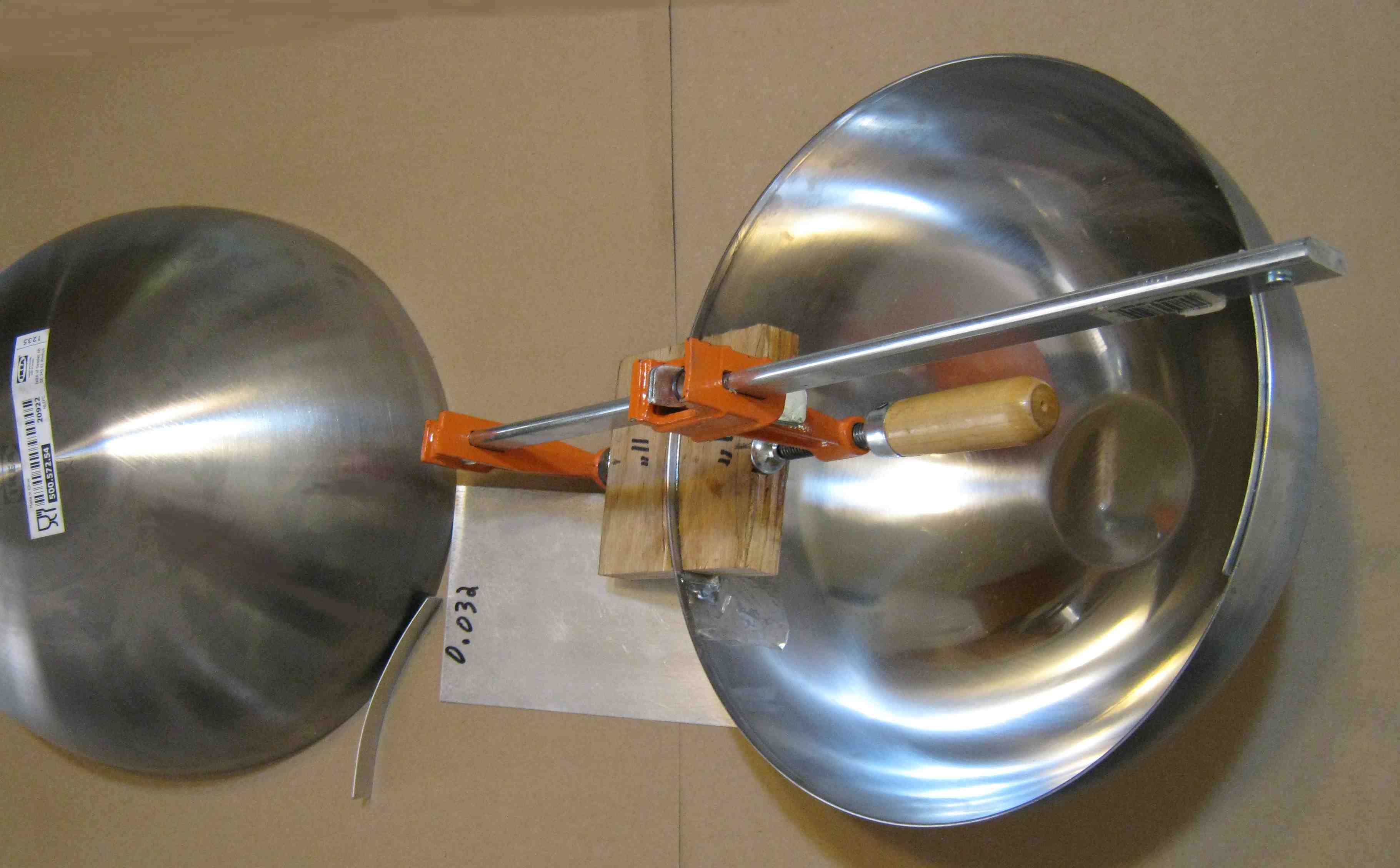
| The upper Terminal is made from two Ikea 14 inch serving bowls (rimless). Strips of 0.032 inch aluminum sheet are glued on one hemisphere to assist in joining the two hemispheres. Surface preparation and cleaning are crucial for good adhesion. Always run adhesive tests so you will not get any surprises after final assembly. |
 |
 |
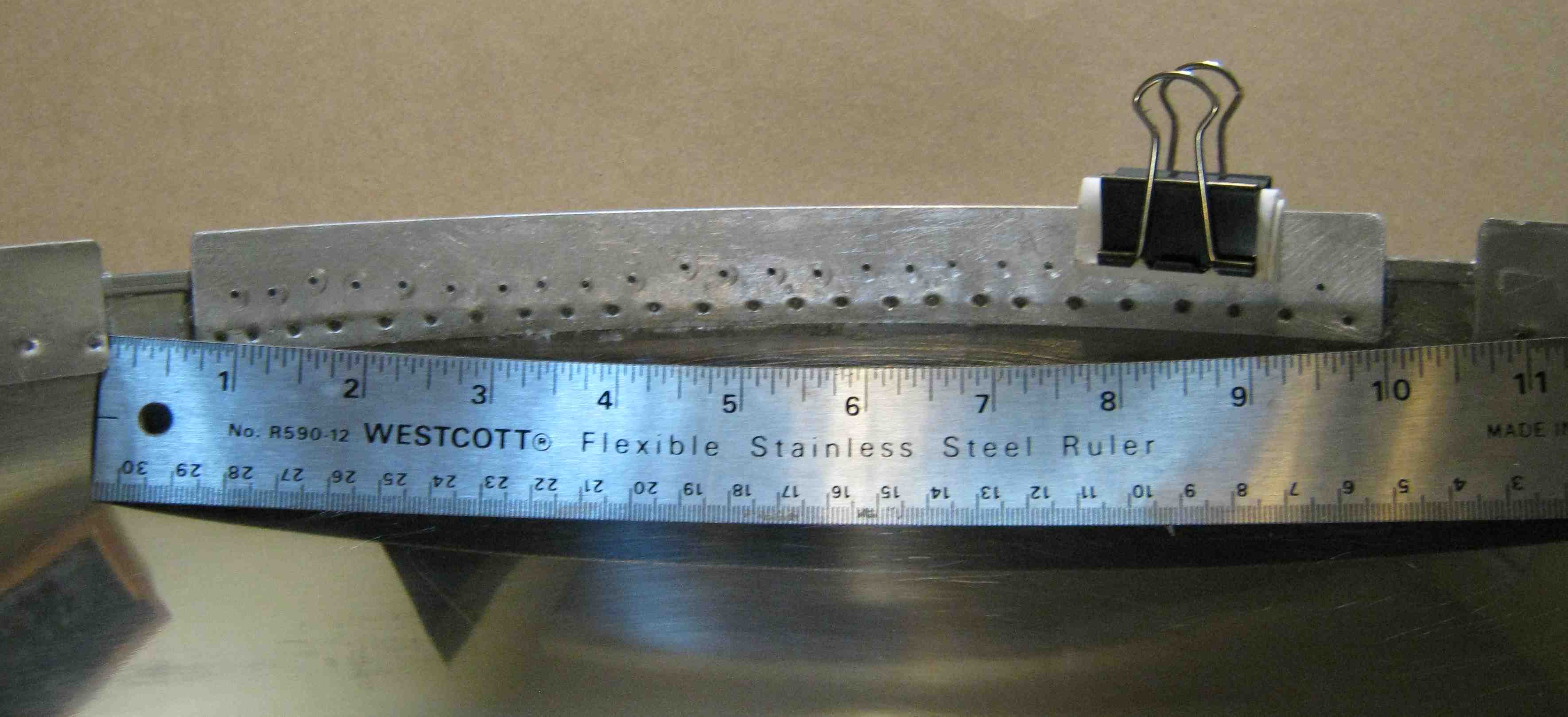
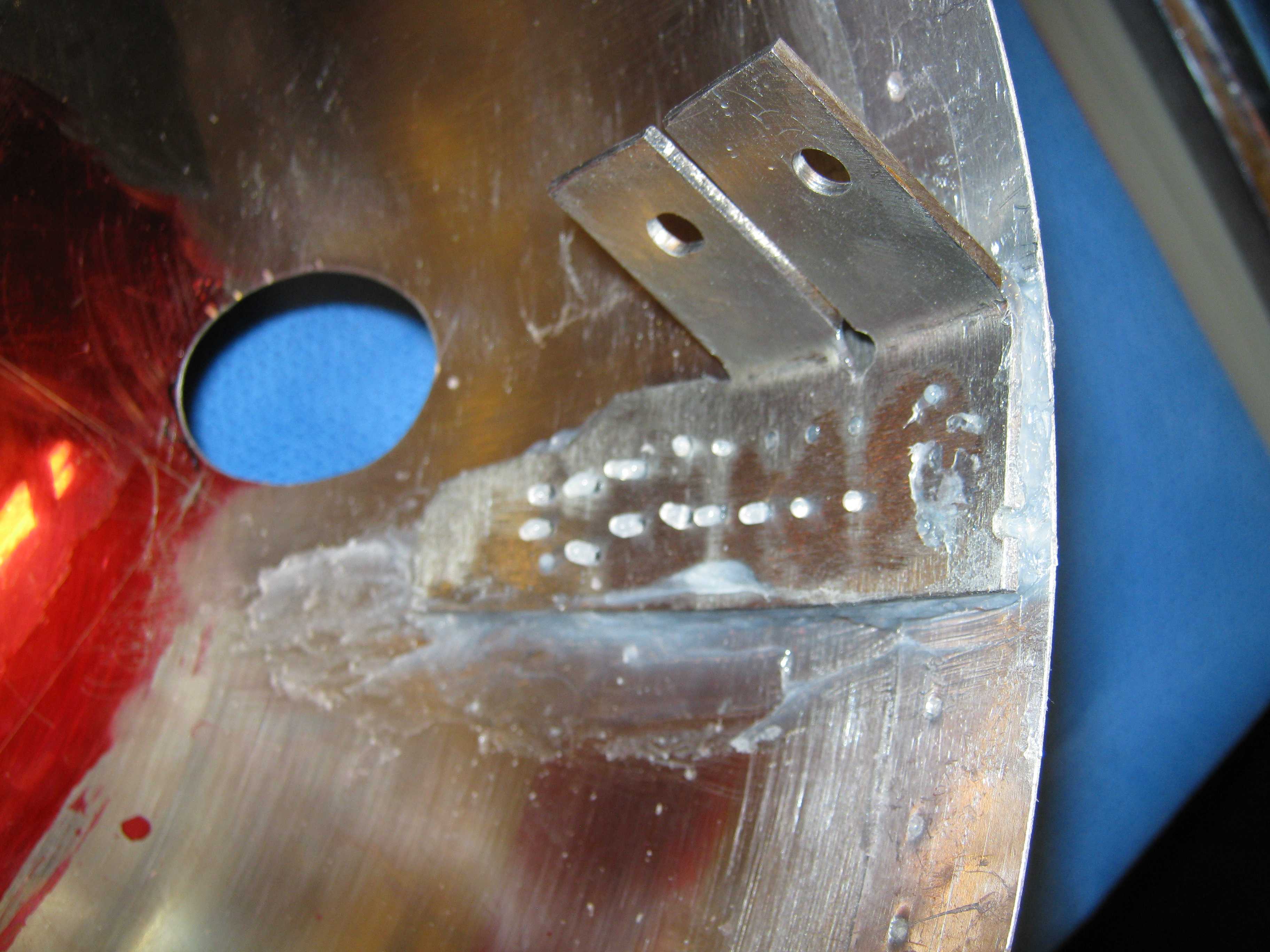
| This is an alternative method of gluing the strips (several clips are used, only one is shown). Silicone I sealant was chosen because it had good adhesion. The holes in the strip are needed to help the silicone set properly. The strips tilt slightly inward to facilitate joining with the other hemisphere. | This is the way holes are located for the supports. Tighten all the fasteners on the upper terminal frame, then place the frame (without the PVC legs) into the hemishpere. Make the frame level (equal offsets) with the edge of hemisphere. With a scribe, mark the points where each corner of the angle iron meets the hemisphere. (Layout dye might be helpful here.) |
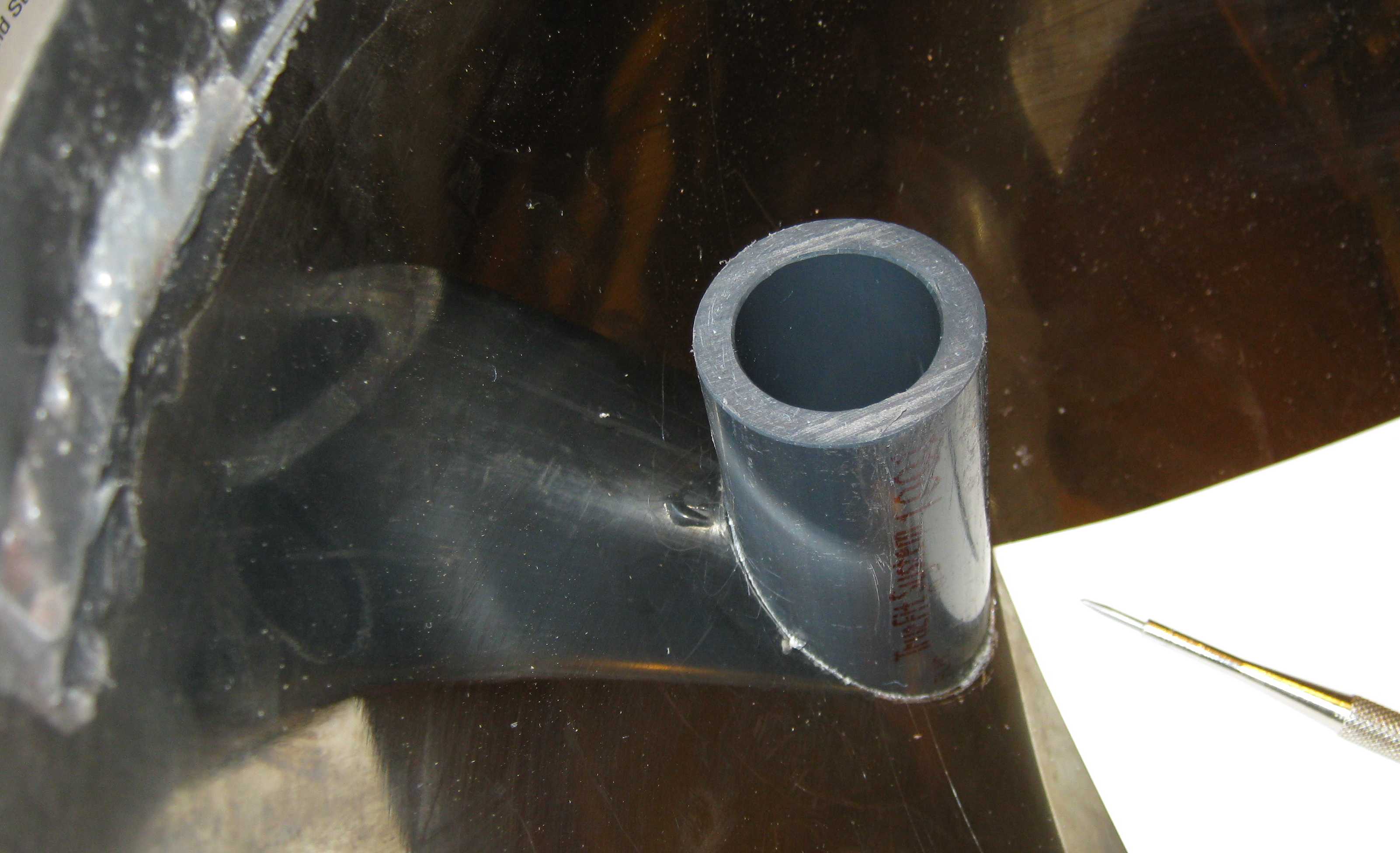 |  |
| A
short stub is cut from 1" ID Schedule 80 PVC pipe at an angle
of
about 46 degrees. It is then glued temporarily to the surface
with 5 minute epoxy and later pulled off. The surface of the
glue
matches the surface of the hemisphere. The stub is then moved successively to each mark made previously by scribing the angle iron corners. The stub is positioned so that the mark is at the high inside edge of the stub, and the stub is vertical. The outside perimeter is then scribed to mark where the holes will be cut for the PVC legs. | After the 4 holes are scribed, they are carefully cut out with a Dremmel tool with a cylindrical tungsten carbide tip. The final shaping is done with a half-round file. |
 |
 |
| The upper terminal frame (with the temporary
legs) is placed into the hemisphere. The holes are trimmed appropriately until all four legs will go through the
holes. Then the whole assembly is inverted. Working from the outside will be easier than working from the inside.The holes are marked and trimmed again until all four legs fit easily and evenly within the holes. |
These mounting pads were made from scrap metal (0.080" shelf
brackets) and do not look quite like the drawing. They are bent
incrementally with a vise and hammer. Note that bending the pad will
cause the two bolt holes to move together slightly and may not match
the holes in the frame. Several small holes need to be drilled so the Silicone I adhesive can set properly. It is best to drill the holes before doing the bending. |
 |  |
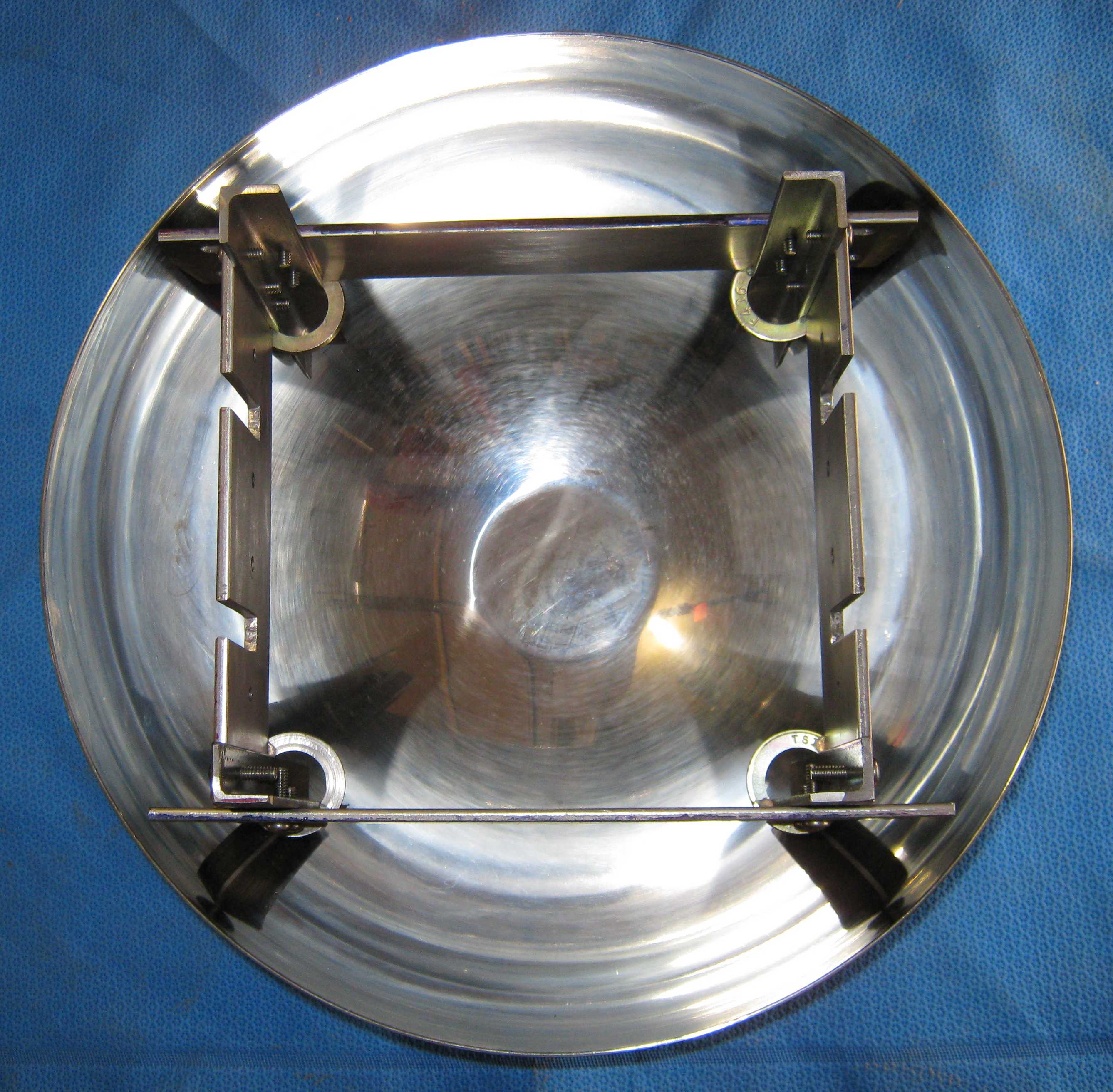
| This is the upper fame before the pads are coated with Silicone I and set into the hemisphere. | This shows one of the four glued pads that are used to attach the hemisphere to the roller frame. |
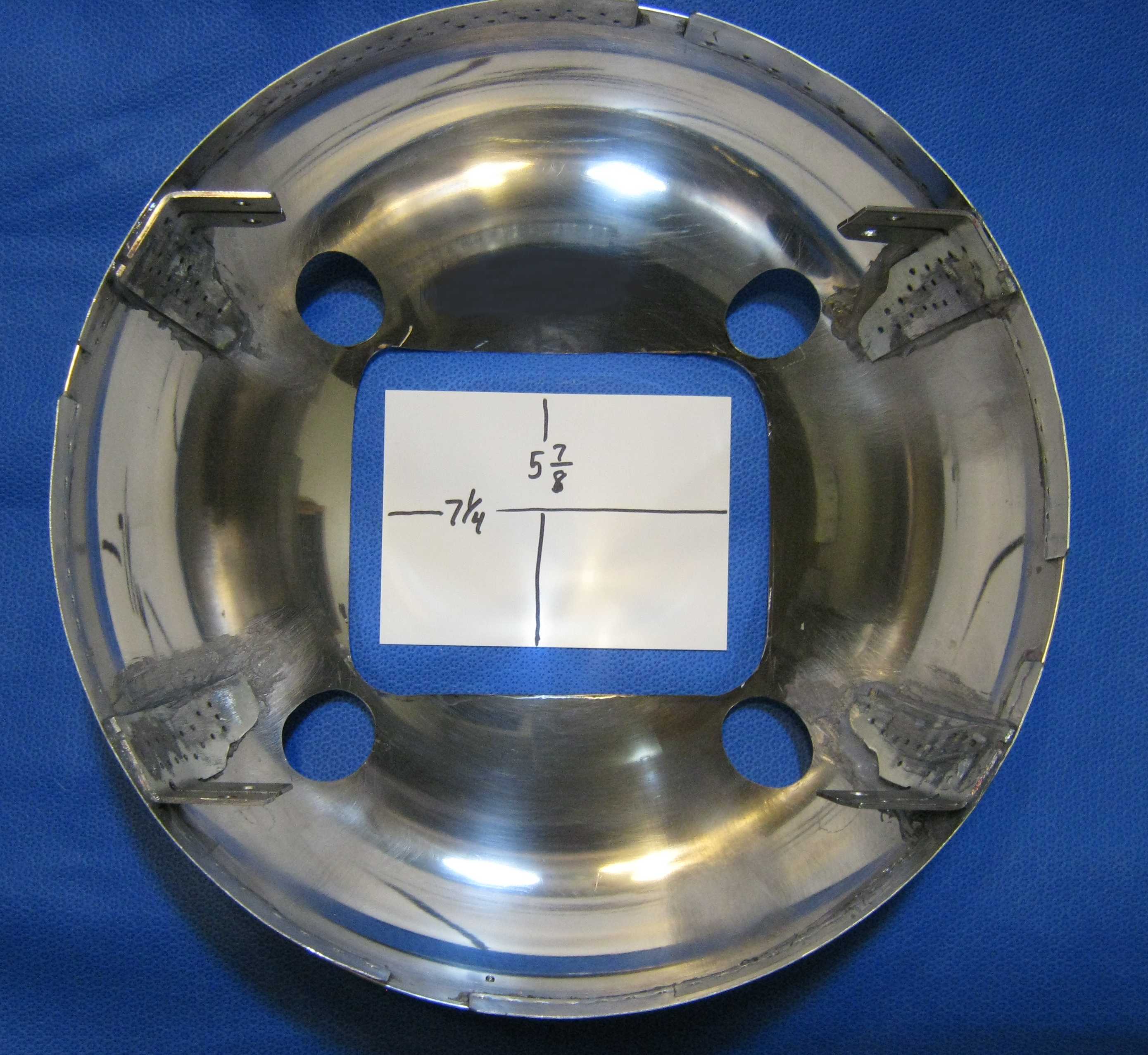 |  |
| This is what the bottom of the upper hemisphere looks like after all cutouts are done. The retangular cutout was done with a disk type cutoff wheel on a Dremmel tool, followed by filing and deburring. | This is what the upper terminal will eventually look like. Note the two rollers and vinyl belts. (This photo is from a belt tracking test; one of the (uncut) brushes is turned upside down) |
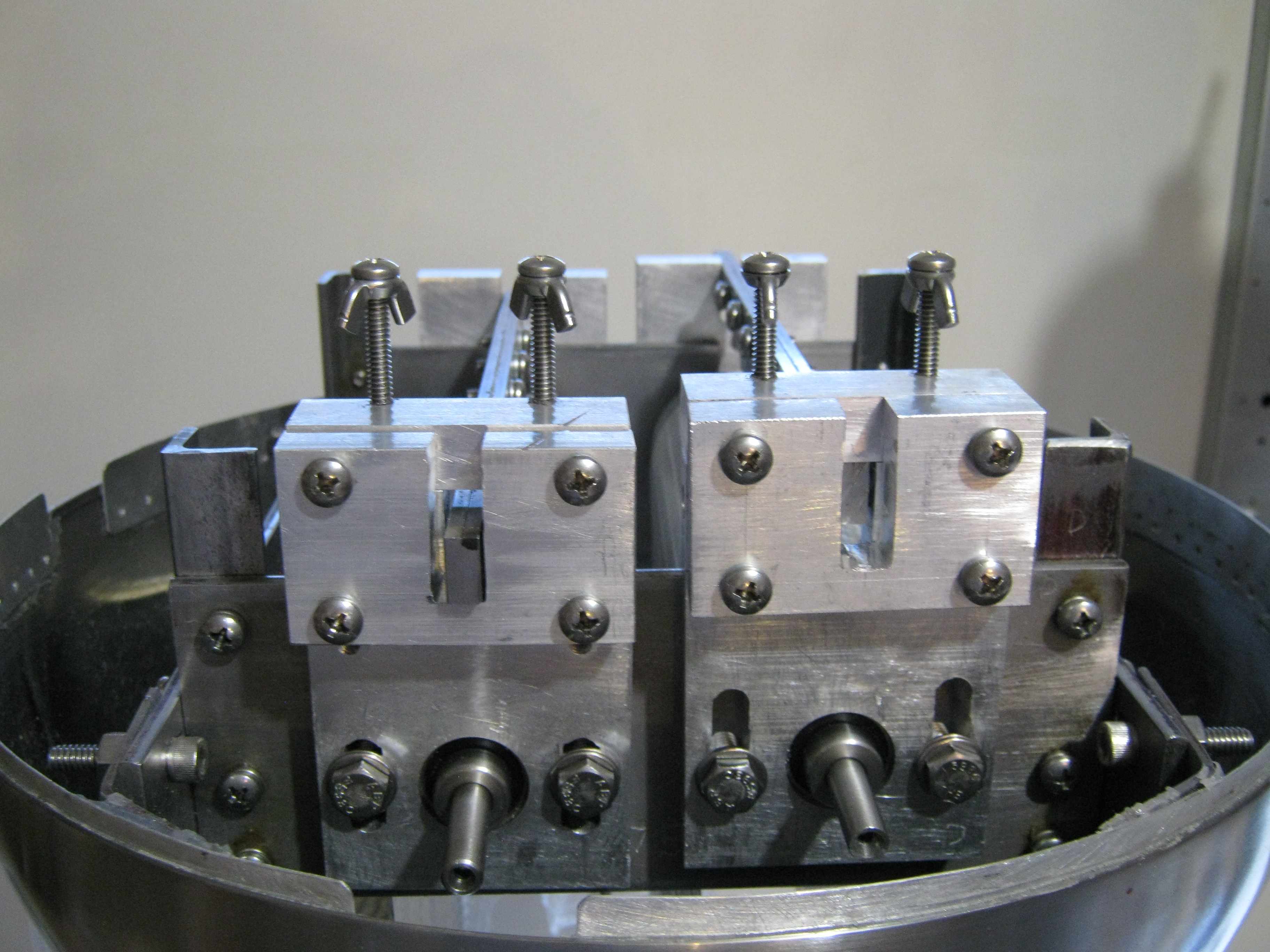 | 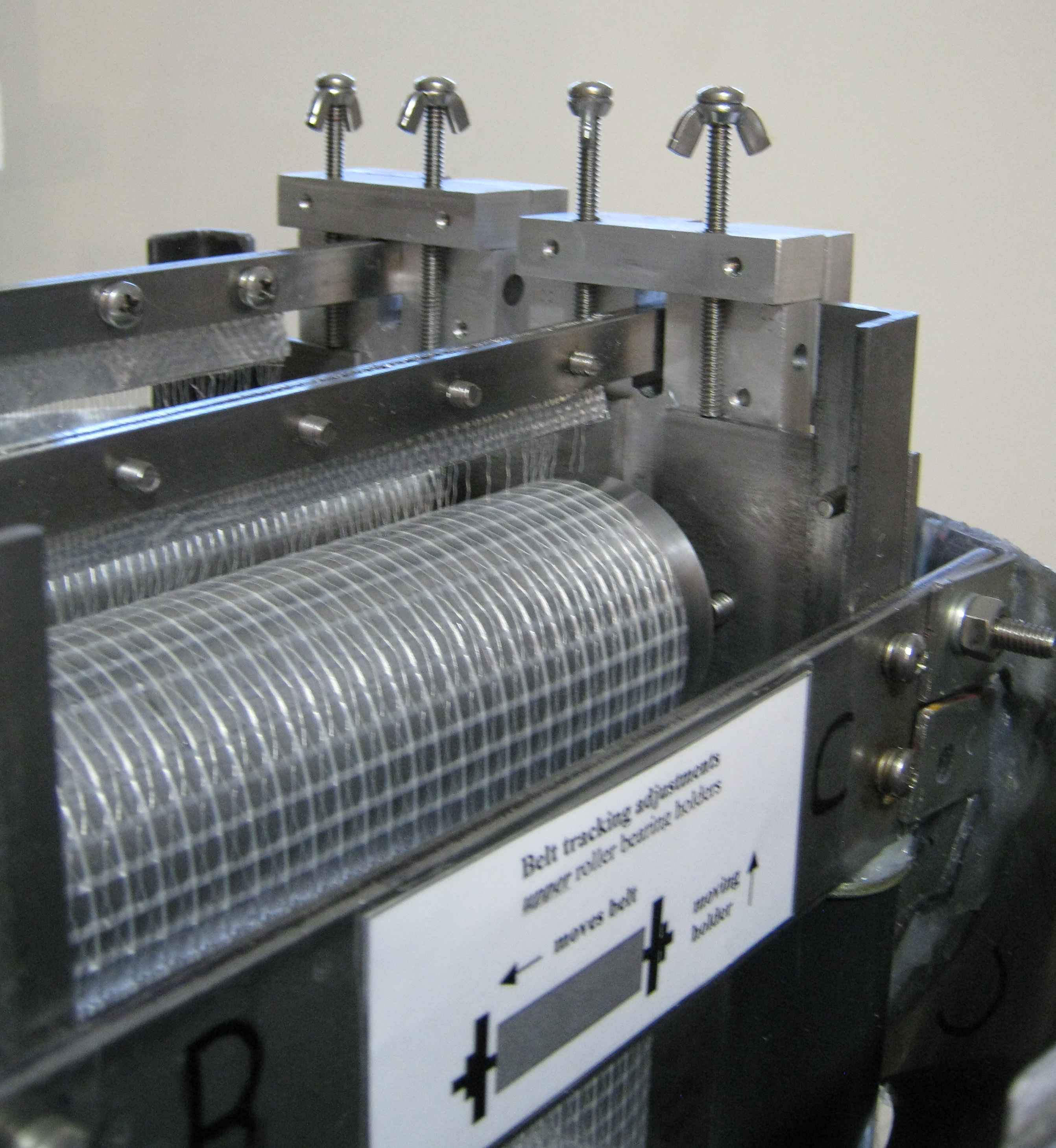 |
| Tracking
adjustments for wide, reinforced belts are more difficult than for
narrow, flexible belts. Here, fine adjustment yokes were fabricated and
bolted onto the upper bearing holders. Coarse adjustments are tested by
spinning the belt and rollers manually. Afterwards, fine adjustments
can be made while the machine is running; both belt tracking and
current output can be observed dynamically. Current output is highest when there is full and forceful contact between belt and rollers. Belt tracking is best when a slight crown is added to the driven roller, but the crown tends to reduce contact force somewhat with reinforced belts. This requires a flatter crown and makes belt tracking adjustment a bit more difficult. The yokes significantly improve the ease of fine adjustment. | The
adjusting screws (shown with up-side-down wing nuts) press down
on the roller frame and pull the bearing holder upward (the bearing
holder mounting screws are loosened slightly). Upward movement of the
roller at this end will cause the belt to drift leftward. Once the
tracking is satisfactory, the bearing holder mounting screws are
retightened. The fine adjusting screws and yokes only need to be on one side of the roller frame because the adjustment is so small. After adjustment, the belt should be checked for adequate tension. Floppy belts will not produce optimal current output. |
 | 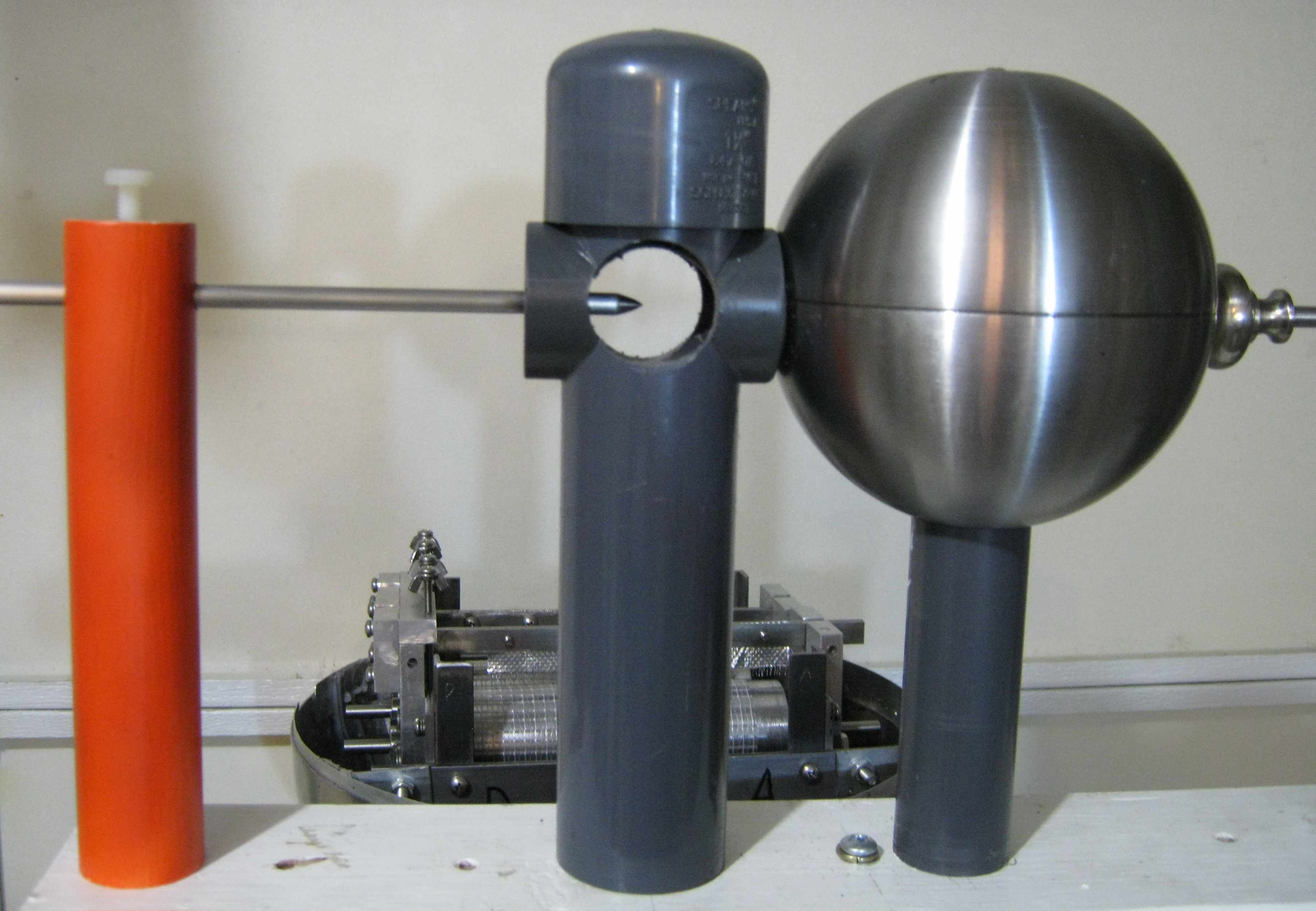 |
| The
spark gap system is mounted on the auxiliary equipment post and is
electrically connected to the upper terminal and a high-voltage
capacitor. Tesla used segmented spark gaps and Piggott used a system similar to the Righi Spark Gap
. Tesla quenched his spark gaps with a powerful electromagnet, which
can today be replaced with powerful neodymium permanent magnets. This
implementation combines the two configurations. The vertical PVC pipe
nearest the sphere contains two 1.5 x 0.75 N52 disc magnets (K&G
Magnetics DX8C-N52) mounted above and below the horizontal spark tube. Both
electrodes are adjustable and can be
connected in various configurations. The central sphere is not
connected to either electrode. For more details see George Samuel
Piggott Effect "Electro-Gravitation" | This scheme at left was later modified to use an open spark gap and a pointed left electrode. The concern was that electrons would be diverted to the side, strike the side wall of the tube, and therefore be diverted back towards the sphere. The open configuration supposedly avoids this problem. The spark path is also visible and shows only one curvred arc; if there were two arcs, curved oppositely in the same magnetic field, this would indicate reverse current caused by an undesirable ringing wave form. |