
|
| The spark gap system is mounted on the equipment post and is electrically connected to the upper terminal and a high-voltage capacitor. Tesla used segmented spark gaps and Piggott used a system similar to the Righi Spark Gap . Tesla quenched his spark gaps with a powerful electromagnet, which can today be replaced with powerful neodymium permanent magnets*. This implementation combines the two configurations. The vertical PVC pipe nearest the sphere with the cap contains two 1.5 x 0.75 N52 disc magnets (K&G Magnetics DX8C-N52) mounted above and below the horizontal spark tube. They are held in place by mutual attraction and by ridges on a partially bored out tube. Both electrodes are adjustable and can be connected in various configurations. The central sphere is not connected to either electrode. For more details see George Samuel Piggott Effect "Electro-Gravitation" |
 |
| The
first iteration of the spark gap had a design defect. The magnetic
field deflected the sparks sideways, but they
ran into the wall of the tube and then continued on to the sphere.
The current was probably not being extinguished as intended.
The design was changed so that electrons would be deflected into
open air instead of the tube wall. And the mushroom electrode was
replaced with a pointed electrode. *Experimenters have considered permanent magnets to be equivalent to electromagnets for purposes of extinguishing an electric arc. However, they might not be equivalent for the purpose of separating electron current from Wyle fermion (or neutrino) current. Permanent magnet fields are conservative but electromagnet fields are NOT conservative. It is well to keep in mind that what might seem to be an unimportant difference might prove to be crucial during attemtpts at replicating certain experiments of Tesla. This apparatus uses a transverse magnetic field. The effect of sparks through a longitudinal field should also be invertigated. See http://scripturalphysics.org/4v4a/ADVPROP.html#MortonEffect |
 |
|
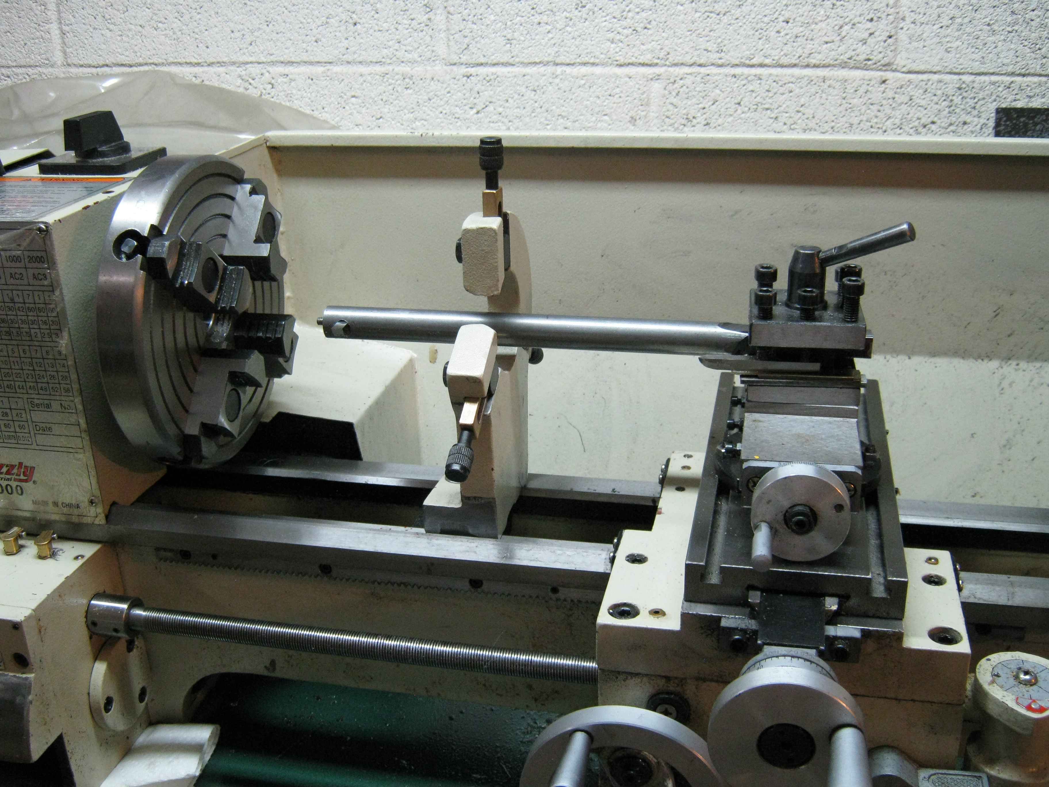
| The
0.75" diameter disk magnets were slightly oversized for the ID of the
vertical magnet tube (not shown). I had to make my own extra-long
boring bar to bore out a few thousandths of ID. The bar is made from
0.75 diameter 1018 steel. A slightly undersized transverse round hole
holds the cutting tool which is pressed through the hole, and held in
place by a 10-24 setscrew at the left end of the bar. Flats are ground
on the right end of the bar for clamping in the tool holder; they have
to be ground so that the edge of the cutting tool will be at the
correct height (which would otherwise be too high). The setup proved to be sufficiently rigid for light cuts on PVC. |