
| I
decided to build the 25kV brush power supply by using an automotive
ignition coil. The main consideration was the supply must have no
semiconductors in the drive circuit, as I was unable to devise a fully
convincing scheme to shield vulnerable semiconductors from intense high
voltage pulsed electrostatic fields. Hence, I chose
to use a
very conventional design based on the old-time (1960s) automotive
ignition systems. These have proved to be very reliable in practice. When I initially tested the van de Graaff, the lower brushes were connected to ground. The voltage produced at the upper terminal was purely triboelectric in origin (vinyl belt on a PVC roller), and I thought I could impove the output (about 80 microamps) by using a sprayed charge scheme. The apparatus below supplied 25 kV (or more) at 100 to 200 pulses per second. Unfortunately, when it was connected to the lower brushes, the tests showed no difference in current output. Hence, for now I have decided not to formalize this scheme. (Afterword: This problem was never adequately investigated. An ignition coil can produce a monopolar pulse but the inclusion of a capacitor across the breaker points will produce a ringing waveform. This will give a robust spark for a spark plug and is fine for automotive use. The ringing itself would not be a problem in this application if the waveform was always positive, but the setup as shown would produce a zero crossing waveform and would not be suitable here. However, a string of series-connected high-voltage diodes was found in the project box a year later. A test procedure was never written, and my memory of these trials is too fuzzy to be reliable. I hope to reinvestigate this problem sometime in the future. (Afternote: the diodes were later tested with a 9V battery, a 100 ohm resistor, and a voltmeter. Tests showed all the diodes were "open" and non-functional. They were NTE517 microwave oven diodes (15kV @ 500ma). These are probably not suitable for fast switching applications. ) |
|
|
| Cam was made from 0.625 square bar stock. It looks like a big bolt with a square head. The points are Honda CA102 CT200 CB92 CA95. The ignition points capacitor was obtained locally. | The cam is driven by a variable speed electric drill. A wood block serves as a bearing and mount. A 12V battery and a "universal" ignition coil, (ACCEL 8140 Super Stack) make up the rest of a very conventional "brute force" 25kV pulsed power supply. |
| An
alternative I might investigate involves coating the lower rollers
with Teflon tape (or Teflon roll covers) because its position
in
the triboelectric series
indicates it should improve the output. As shown in the table below by
Alpha Lab, Inc., the nC/J values for vinyl, PVC,
and Teflon
are -75,
-100, and -190, respectively. The present output (80 microamps) is
based on the difference between -75 and -100 (a difference of only 25).
With a Teflon coated roller the numbers would be -75 and -190, a
difference of 115; this implies a factor of 4 improvement ,
and
possibly a current output as high as 300 microamps. This would
significantly improve the repetition rate--something crucial for
Project Whitefire experiments. Inspection of the table shows that other
combinations could go as high as a factor of 10 (800 microamps!).
(The problem is in locating materials, and maintaining
reliable
performance. )
See below. Another thing the needs testing is the position of the brushes on the lower belt rollers. Should they be along the bottom of the belt, or should they be where the belt separates from the roller? The latter seems to be more logical (but later tests showed no significant difference in performance). |
 |

 http://www.americandurafilm.com/film-distribution/heat-shrinkable-rollcovers-saint-gobain/ |
 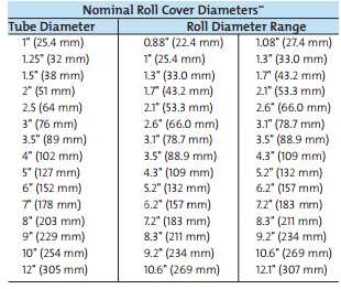 http://www.fluoron.com/salesbook/FEP.pdf http://www.fluoron.com/salesbook/FEP.pdfhttp://americandurafilm.com/data-sheets/rollcover-data.pdf |


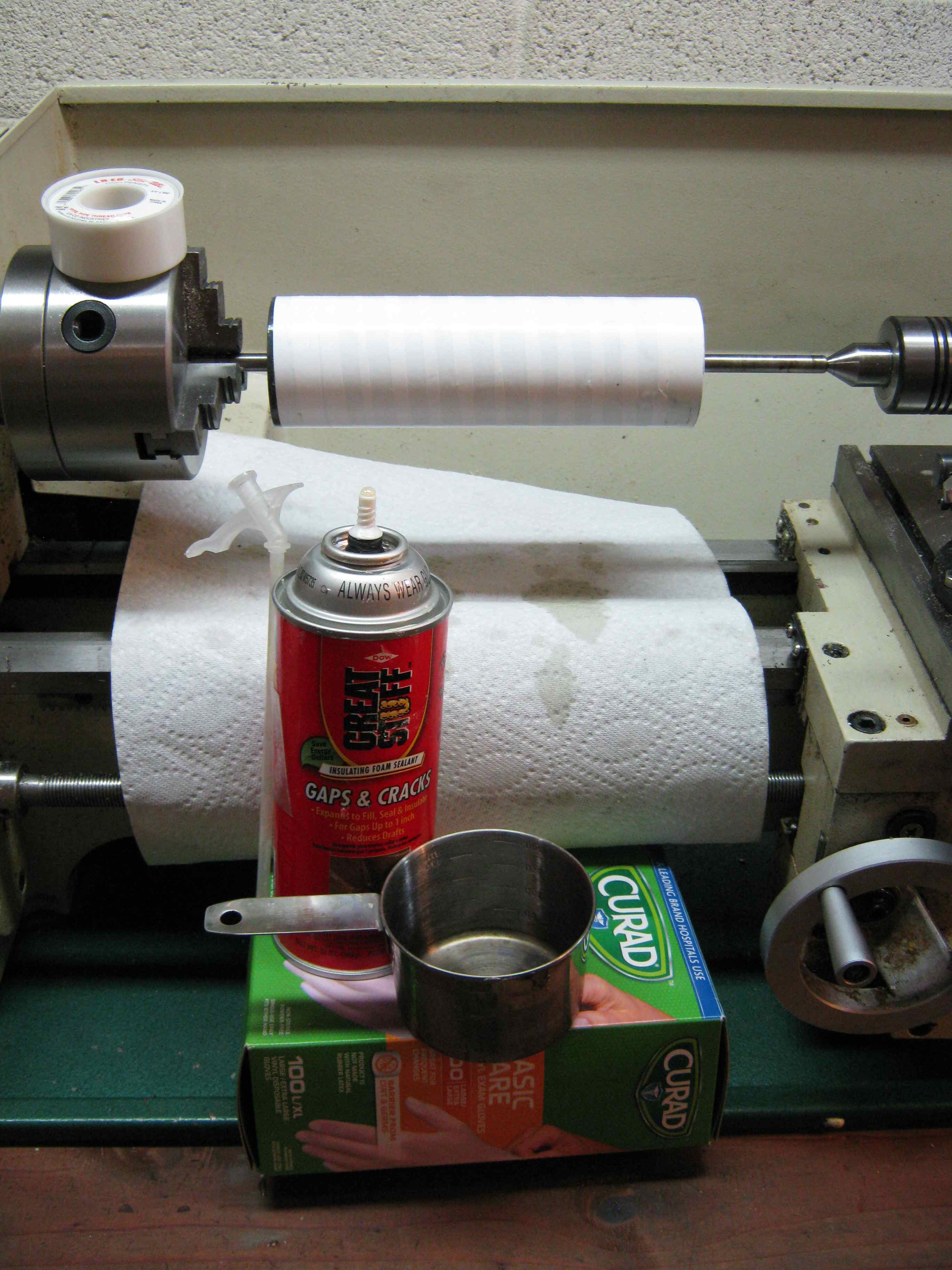 | |
| This is a test of Teflon tape wrap. The "glue" is uncured polyurethane foam dissolved in a small amount of acetone. It is smeared (use vinyl gloves!) across the entire roller and then the roller is wrapped with 3/4" wide Teflon tape. The direction of the wrap is such that the torque will tend to tighten the tape. The lathe is unplugged and is only used as a convenient fixture. |