| |
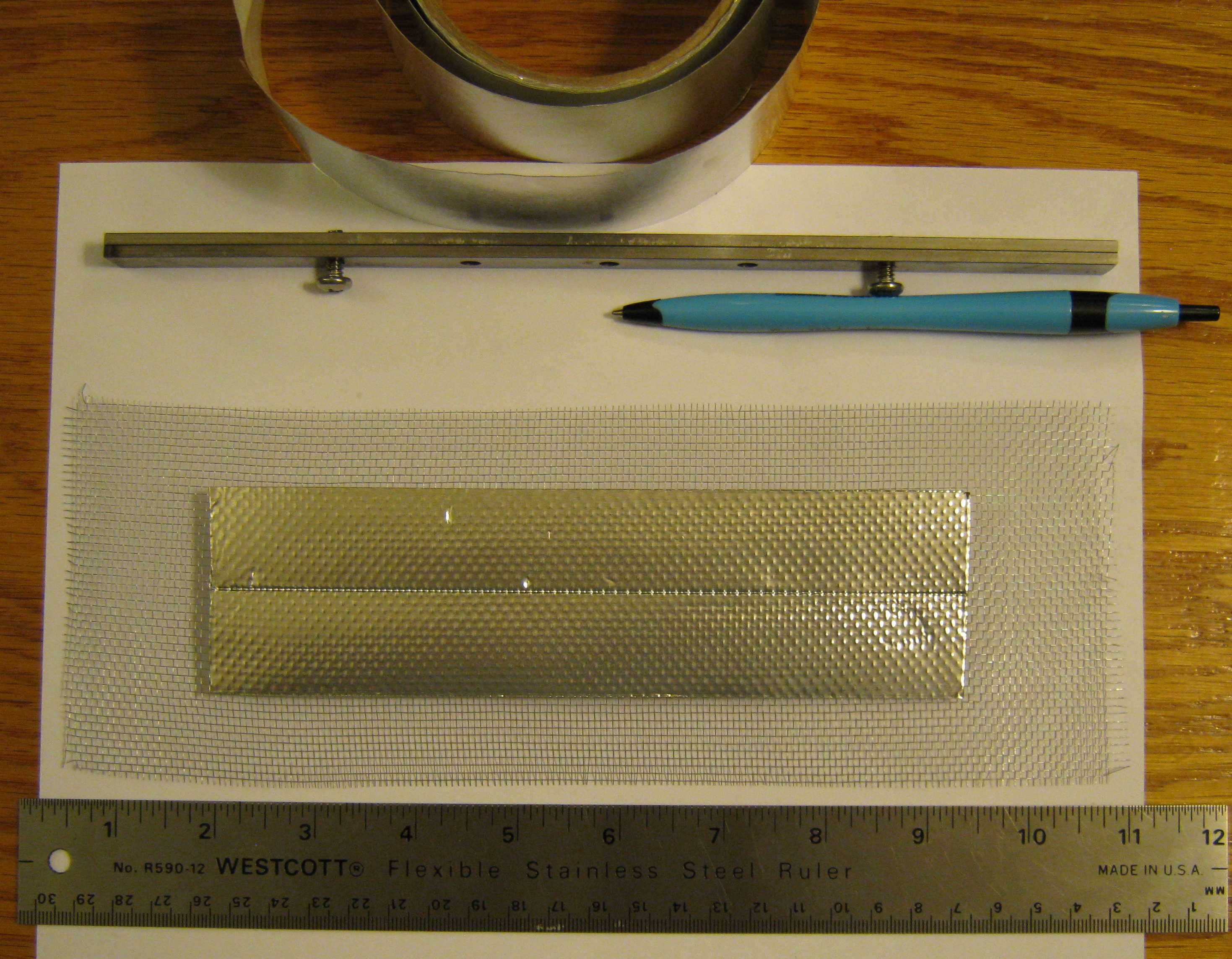
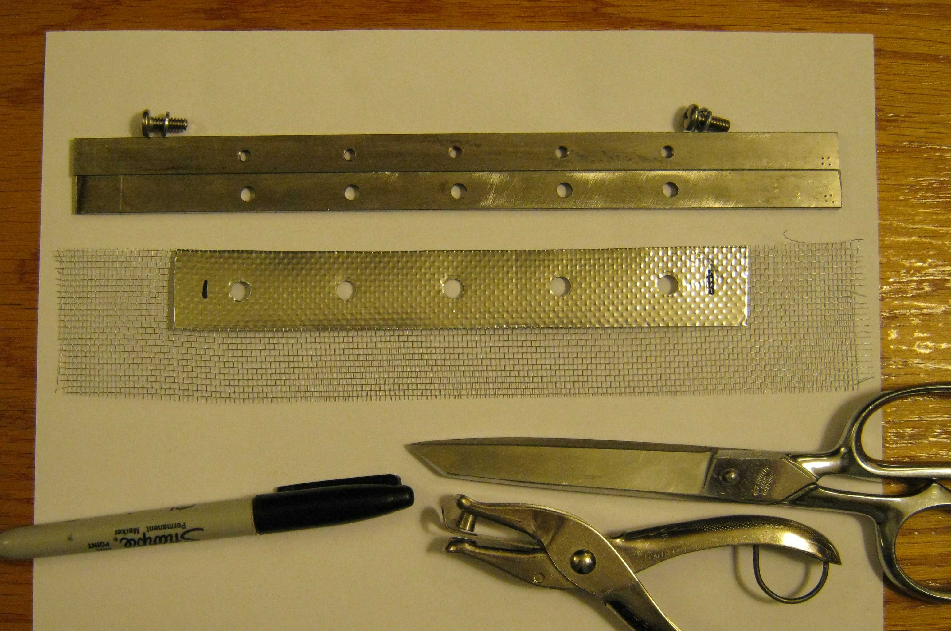
| Basic method of making a brush consists of sticking metal (heating) tape 2 inches wide on both sides of a piece of aluminum wire window screen that is about 10 inches long and 3 inches wide. Both sides are taped to balance out forces that could cause curling. This piece is about to be cut in two, to make two brushes. | Holes for the screws are marked and cut with a paper punch. Screen will be trimmed to 6.5 inches. |
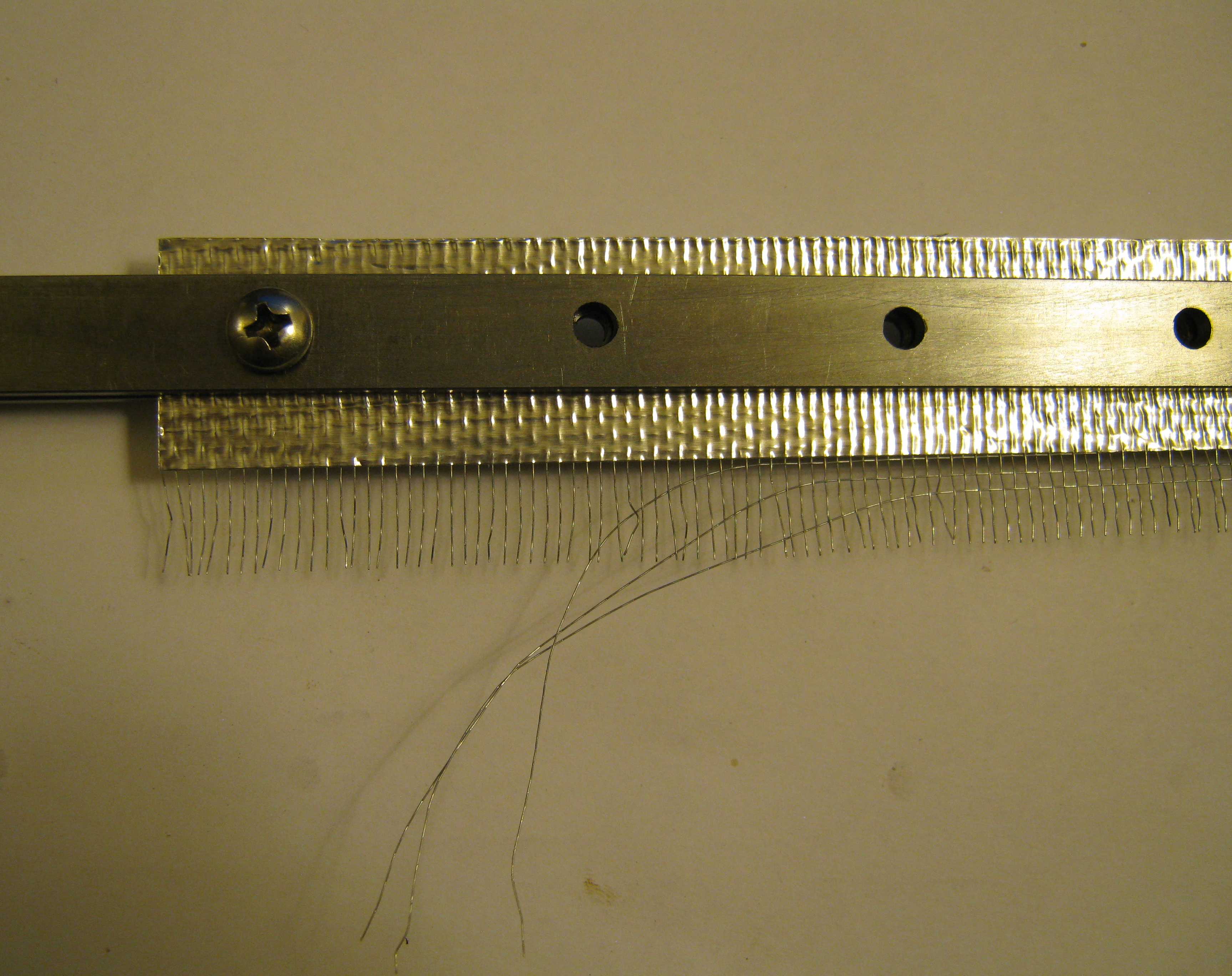 |  |
| Some longitudinal wires on the screen will be pulled out to make a brush comb with HV emitter points. Brushes are fragile, and so combing and trimming are normally done just before the brush assembly is mounted into the machine. All remaing wires must be held secure by the tape so that they do not work loose with vibration. | The ends of the brush holder are marked with shallow hacksaw cuts to facilitate correct assembly. Lockwashers are used on all fasteners to keep the assembly in compression; thread locking compound (blue, medium strength) is used to secure the screws. |
 | 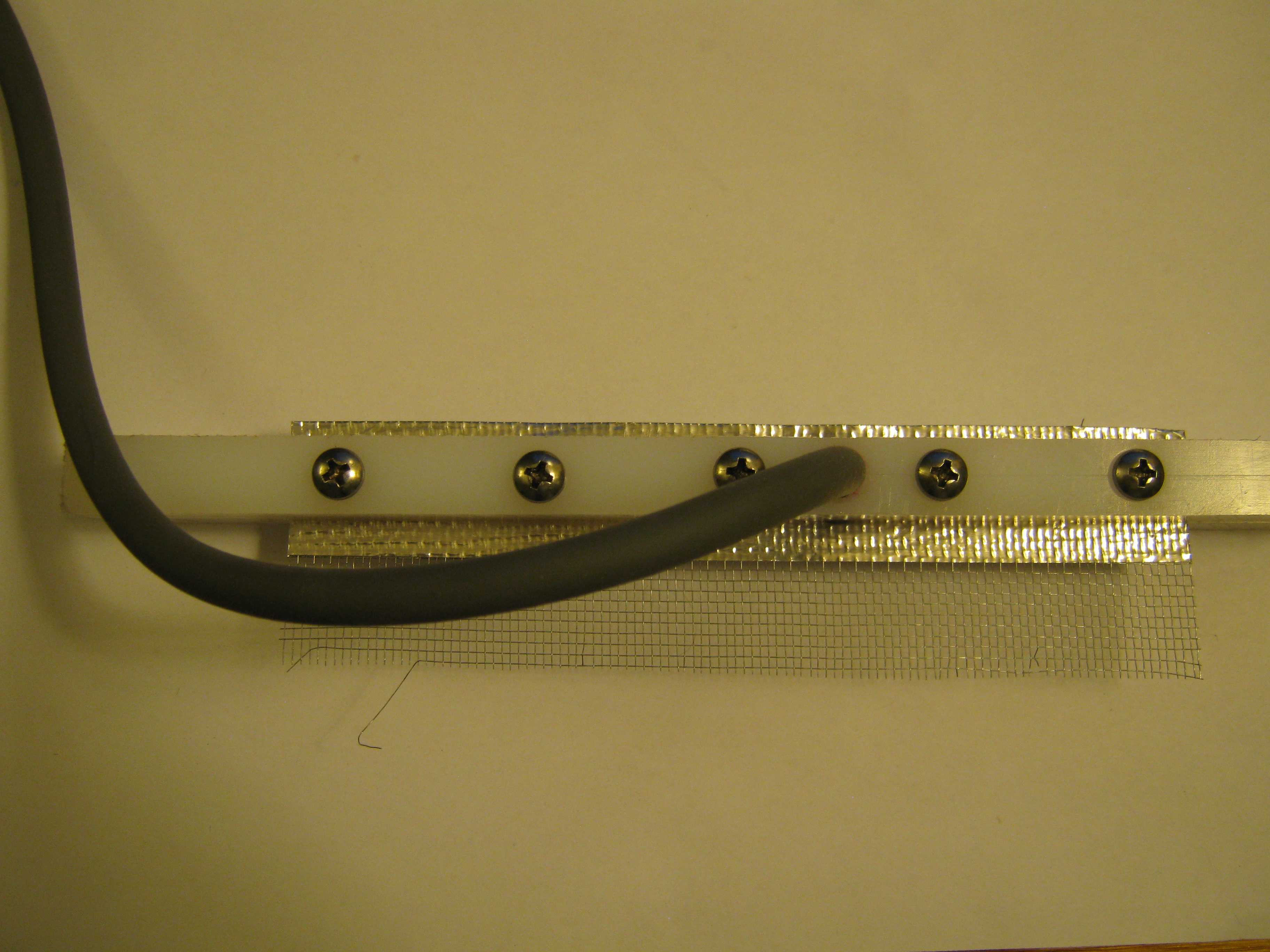 |
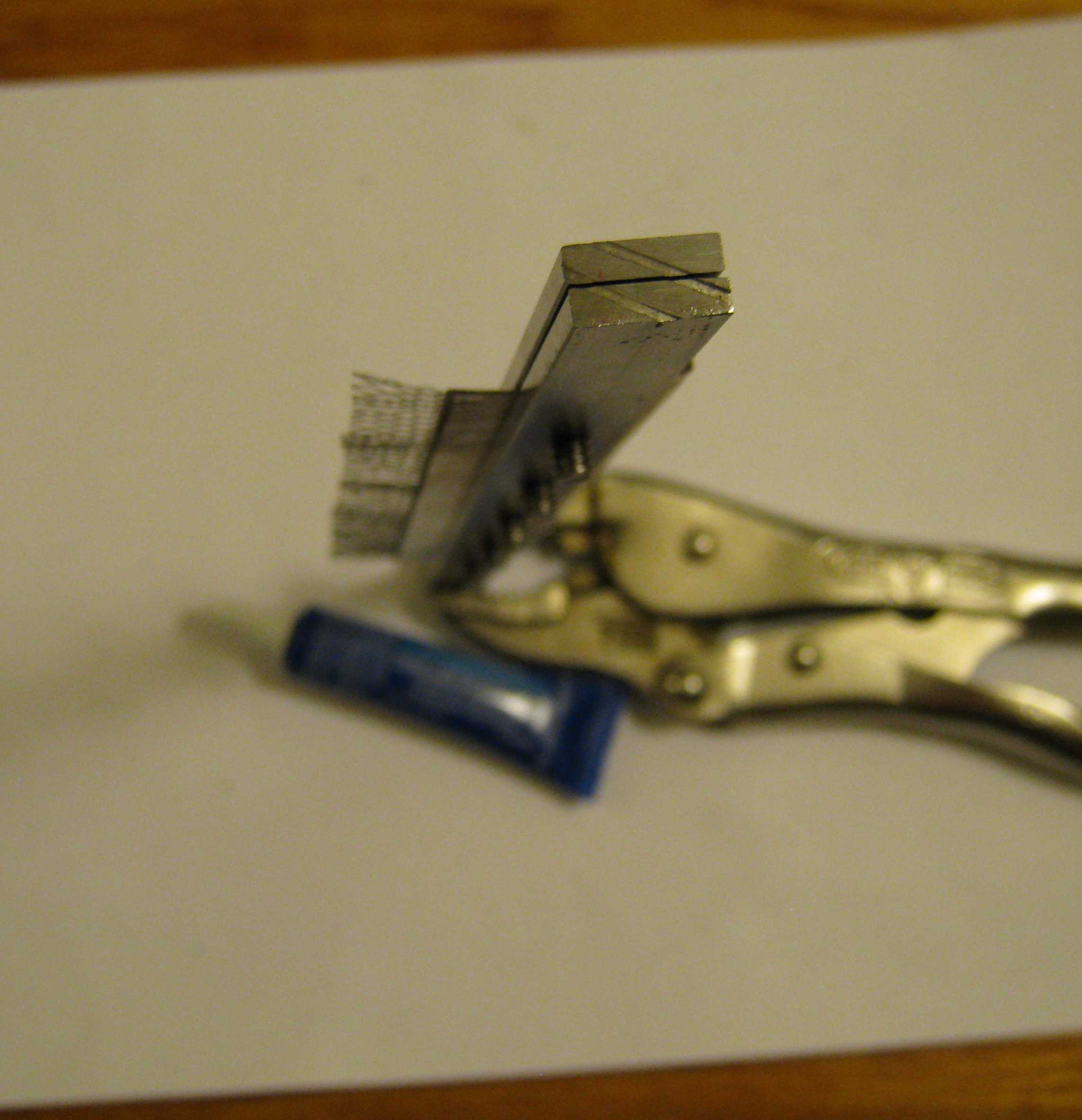
| The lower 25,000 volt brush holder is made from nylon or similar plastic. The brush itself is assembled in the same manner as the upper brushes, except that an additional hole is made for the ignition cable. Note the transverse pin that both secures the cable and connects it to the foil. | This is one of the 25,000 volt brush holders before final combing and trimming. |
 |  |
|
Coil driver contains the Pulse Width Modulator module which drives the ignition coil module (not shown). Power, coil module, and fan are not connected. The duty cycle pot controls the current that charges the magnetic core of the coil and therefore the milliamps of the HV output. The frequency pot is set almost to the upper limit of what the ignition coil can accept (about 300 Hz). Supporting
components include a power supply decoupling capacitor, a reverse
polarity protection power diode, fuses and a switch. The upper terminal
strip is positive, the lower is negative. |
Photo
of the impromptu spike suppressor. It consists of two zener diodes in series to
begin clipping at 320 volts. A 1N1004 diode is in series to block normal coil
supply voltage. The diodes only conduct on “kick back” from the coil. The
zeners have a fast response, but the 1N1004 is an ordinary diode, and so each
diode is bypassed with a 1200pf, 1kV ceramic capacitor to allow for commutation
delay. |
 |  |
| A cooling fan is mounted on the outside of the lid and blows air through a big hole which may expose sensitive electronics to intense electric fields. A wire screen must be made to cover the fan. Fabrication starts with a 7.5 x 7.5 inch section of 1/4 inch screen. | Ends are folded inward to make a box-like structure. |
 |  |
| Wires are bent over to secure the fold. Other protruding ends are cut off. | Screen and fan are installed on lid with 6-32 x 2" screws and 7/8" fender washers. They are each secured with a lock washer, a nut, and thread locking compound. |
 |  |
| The
nuts and flat washers in the middle are run down flush with the fan
housing and secured only with thread locking compound. The screws
holding the whole assembly to the lid are secured with lock washers,
nuts, and thread locking compound. The fan is positioned directly above the PWM circuit board. It is very important that no metal filings, clippings, fasteners, etc., fall onto this board during operation. | Photo
of interior of Ignition Coil module as a test setup. It consists of an
ignition coil and two capacitors which are wired across the ignition
coil primary terminals.The capacitors catch most of the
electrical "kickback" from the coil. (The paperclip inside the HV
terminal is for testing.) This setup will work okay with cam
driven mechanical "points" such as those used in the automotive
distributors of former times; this facilitates simple manual testing by
momentary connection/disconnection to a battery. |
 | |
|
Location of upper brushes. Brush 'B' is in its final
position. Brush 'A' has not been trimmed or combed; it is mounted
upside down temporarily during a roller alignment test.
| Location of lower brushes. |