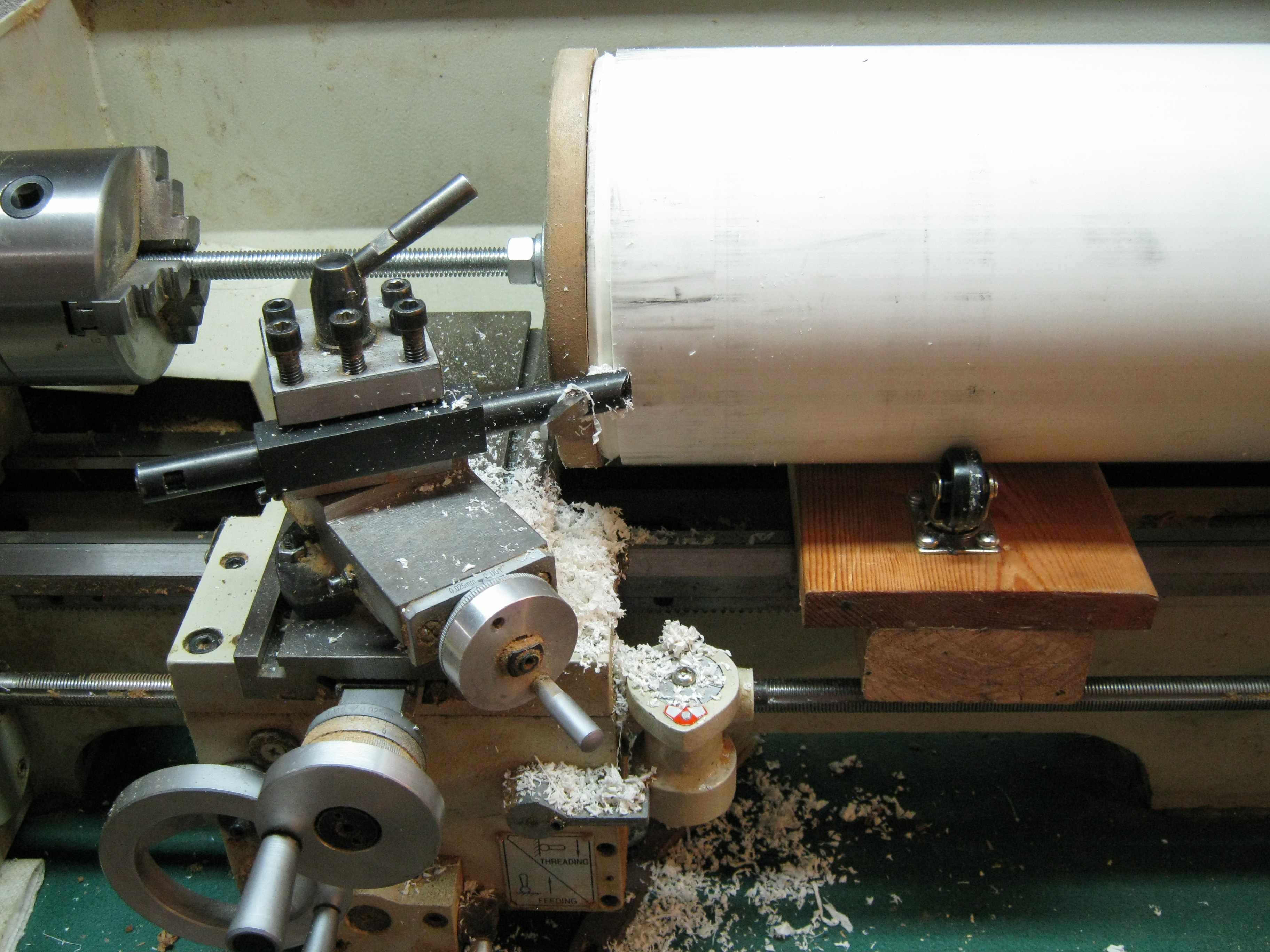

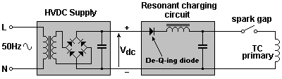
The lathe is set to its lowest speed, and only slow feeds are possible with this arrangement.
The Tesla primary coil will later be slid inside this tube.
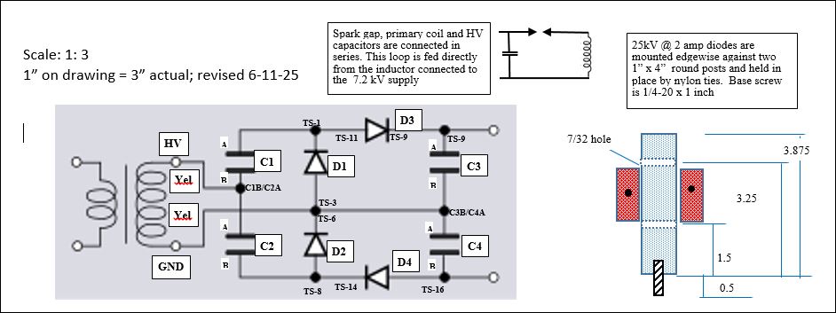
| |
| The
design required end-facing a 5 ft. long 6.625" OD tube. But how is this
done on a 19" lathe? The tail stock was removed and a temporary "tail
stock" was made from a wood post, a 1/2" steel rod, and a base to mount on the work bench.
Two casters are needed to support the tube at the chuck end because
there is not enough clearance to move the carriage under the tube. An
"end buttress" (also used in the final assembly) is clamped on a
long threaded rod and is used to drive the tube from the chuck. The lathe is set to its lowest speed, and only slow feeds are possible with this arrangement. | Axial
and radial alignment must be carefully done for this arrangement to
work. The two casters and the "tail stock" must hold the tube at the
correct height and angle. Paper shims can be used to raise the height of the
caster plate if it is off slightly. The lathe's hollow chuck can be used as a "bore sight" to
get the "tail stock" close to its correct position, and correct angle.
If anything is out of alignment, the buttress cylinders will emit creaking
noises and will gradually work their way out of the tube. Torque requirements will also increase. The Tesla primary coil will later be slid inside this tube. |
 |
 |
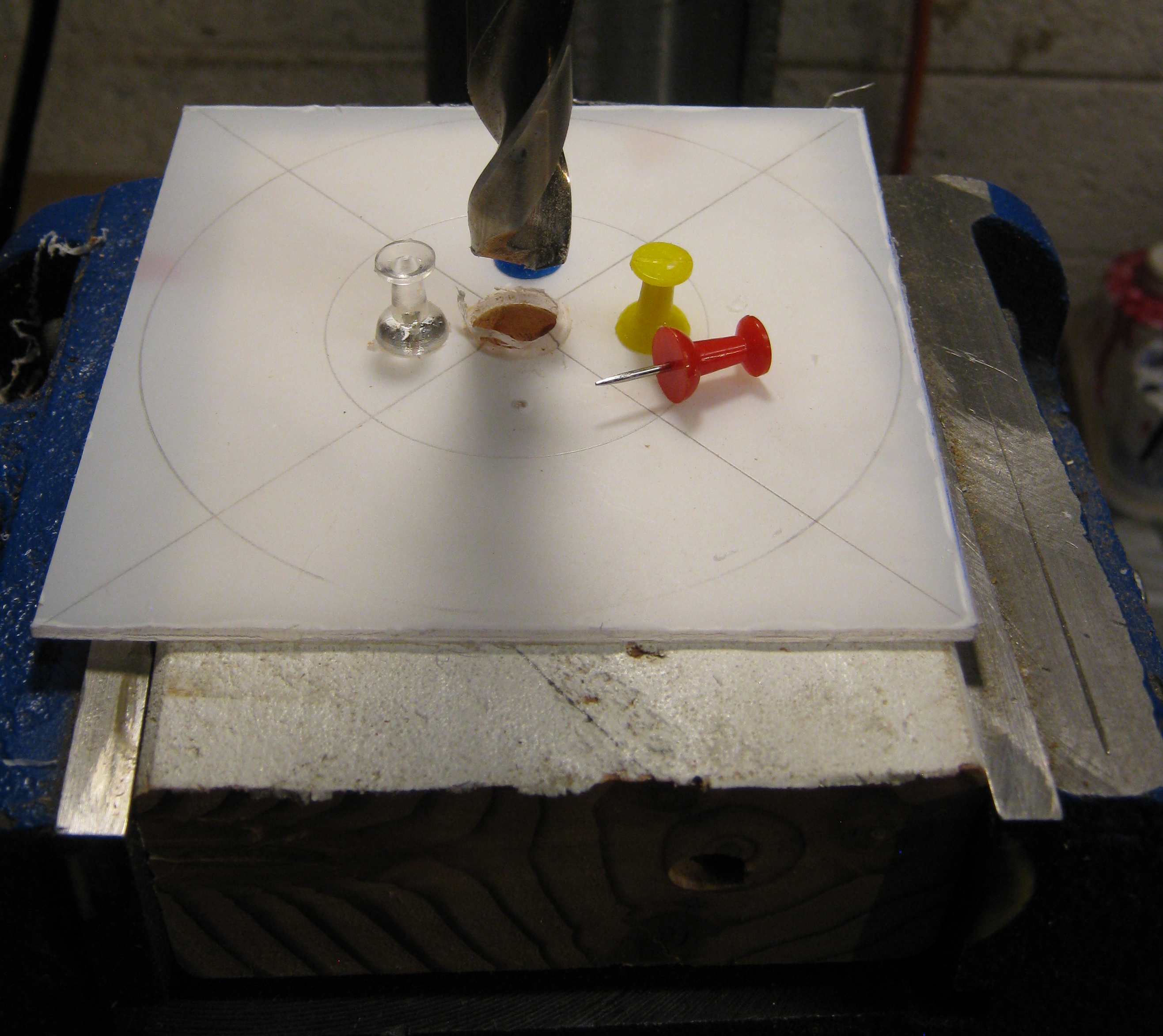
| A special fly cutter had to be made to cut an opening
in
the 11" serving bowl bottom. The hub was made from a length of 2.5"
steel bar stock, and the transverse tool holder was made
from 3/4" steel bar stock. The bit holder
itself was made by drilling an 11/32" hole in the bar and then pressing
a 1/4" lathe cutting tool bit through the hole. Three 1/4-20
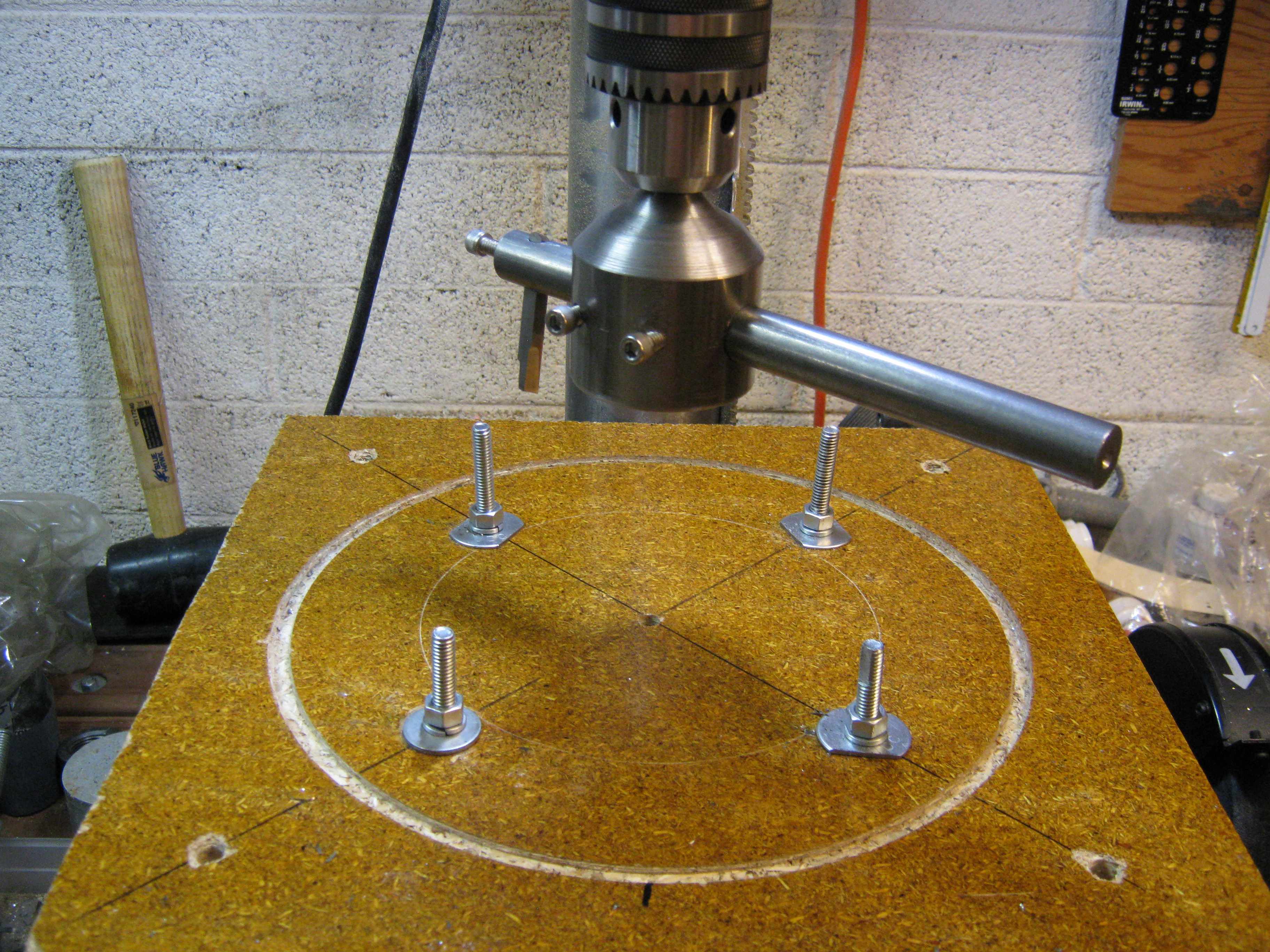
screws anchor the bar and the tool bit. A wooden plate is bolted to the drill press table. A central hole is drilled in the plate to facilitate alignment when the table has to be moved up or down (it can swing sideways). A circular groove was cut to anchor the edge of the serving bowl. |
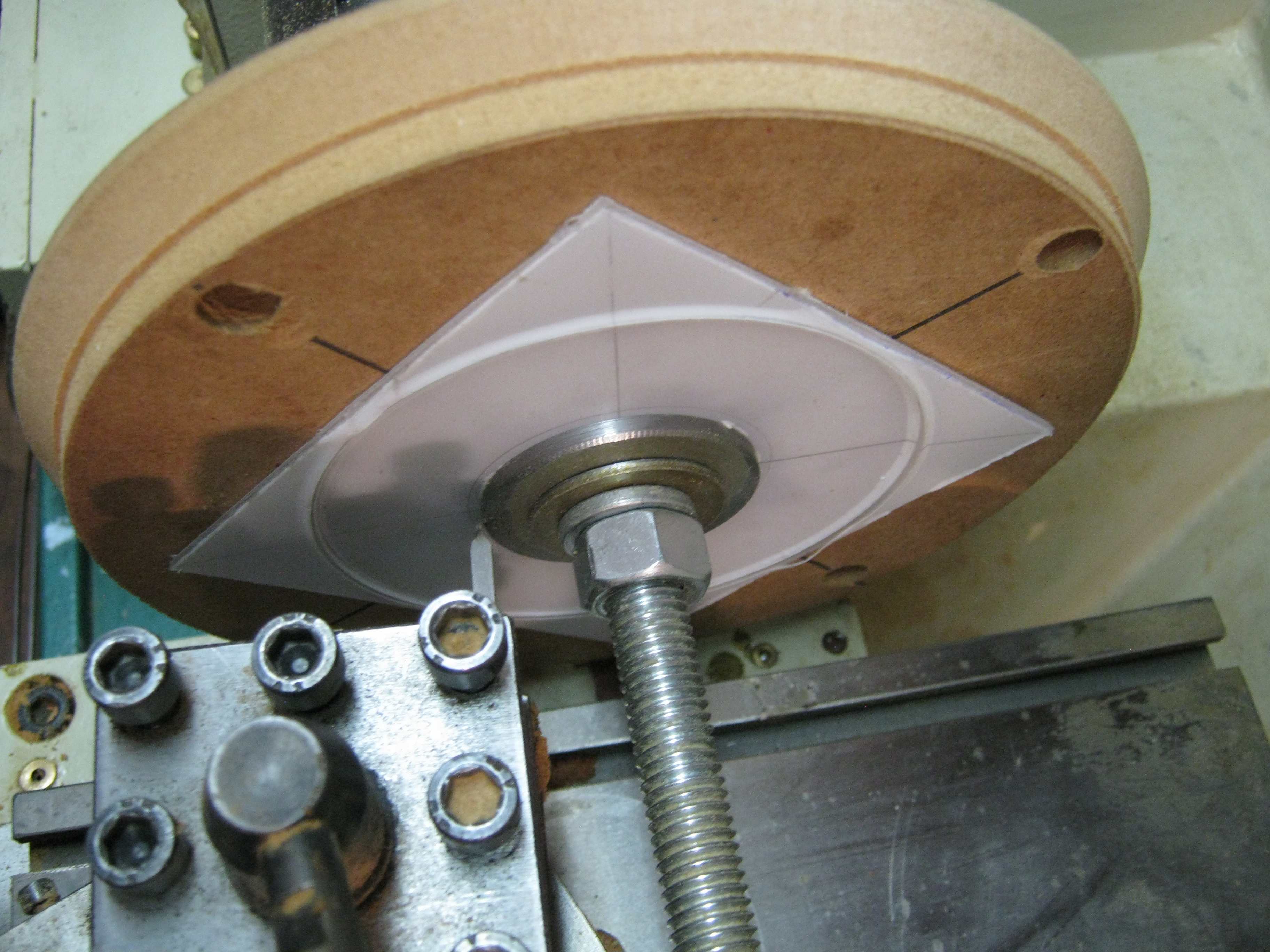
Another 3/4" wooden plate (MDF) has a large circular
hole cut into it to firmly hold the bowl against the bottom
grooved plate. Here the 11" metal serving bowl is clamped in the fixture and a circular section (6.75" ID) has been cut out of the bowl. This scheme requires rigid fixturing, a sharp cutting bit, the lowest drill press speed, slack drive belts, and a tool bit setup to lean slightly backwards so that it drags while cutting. This prevents the tool bit from digging into the thin, easily deformed metal, but results in a noisy, chattering, cutting operation. The hole is still a lot better than what could be produced by hand. It is finished by filing and sanding. |
 |  |
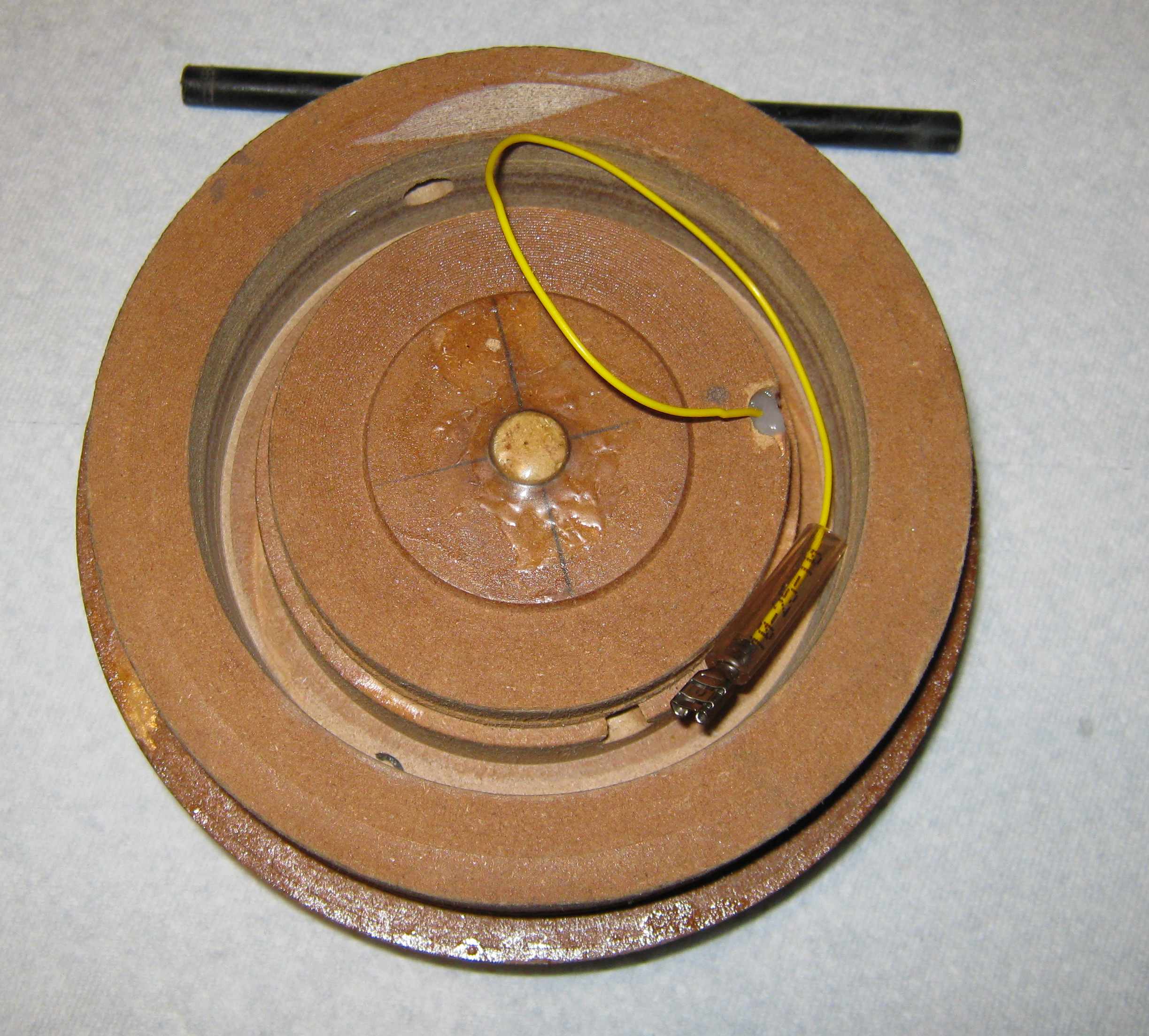
| End caps are made from a stack of five 0.75" MDF (Medium Density Fiber board) glued together. The pieces are cut from a board, then center drilled, and then the corners are cut off each piece (this greatly reduces lathe turning time and a mess of chips).They are aligned with a 0.25" piece of rod and are then glued together. | End
caps couple the curve of the bowl to the flat end-buttress. The
bowl is 11" in diameter (rim to rim) but the bowl curve itself is
actually about 11.5". The depth of each cut was calculated on a
drawing and then the carriage feed dial was used to make each cut to
the correct depth. Both the end caps and the end buttresses were made from three plies of 3/4" thick MDF . The plies were glued together and then carefully drilled in a drill press with a 15/32" drill to create a slightly undersized perpendicular center hole. The glued disks are mounted on a 1/2" threaded rod, and then the surfaces are end-faced in the lathe so that they are both perpendicular to the rod. This precedes any other machining operations The lathe tail stock, not shown, is used in this operation. |
 |  |
| The
plateaus were evened out with the compound feed and then final
smoothing was done with a coarse file. The profile is matched to that
on a drawing mounted on a piece of cardboard. The nut, washers, and tail stock must be removed to cut a flat for the flat portion of the bowl, which protrudes inward about 1/16". During final assembly the end-cap is mated with the buttress by a 1/2" wooden dowel. | The methods shown above were too cumbersome. A much faster and just as accurate method used a wood plane and a visual match to a template. |
 |  |
| The
end bolster and curved end cap are joined together by a 1/2" wooden
dowel, and plenty of acrylic spray (these were later made as one
piece). A hole is drilled in the dowel for a coupling nut which is then epoxied into the hole. A 10-24 screw is used to attach the spherical electrode. Note that there are no electrical connections to the center screw. A shallow strip of MDF is chisled out to accommodate a brass electrode. | The brass electrode strip is soldered to a multistrand wire and then glued to the endcap. Two small brads (not shown) help to anchor the strip in place. |
 |  |
| This
is what the inside of the buttress+endcap looks like. The cap holds the
4" ID tube and the 6" ID tube in alignment and serves as a mounting
surface for the spherical electrodes. The black nylon 3/8" rod goes
through transverse diametric holes and anchors the cap to both tubes
and resists longitudinal slippage. The wire is terminated with an ordinary spade connector. | This is a side view of the buttress+endcap. The ends of the brass electrode are bent up slightly to insure contact with the spherical electrodes.. |
 | |
| A 3/8" hole is drilled freehand with an extra long drill bit. The endcap is held flush with the tube by using packaging tape. The card serves as a drill guide so that the hole will be straight across a diameter. |
 |  |
| Strips
of aluminum (10" x 1" x 0.032" ) on one hemisphere serve to mate the
two hemispheres into one sphere. The strips have 1/8" holes
drilled 3/8" apart and 5/8" from the top edge to speed the setting of
the silicone I sealant. The stainless steel surface must be
roughened with 60 grit sandpaper, cleaned with household scouring
powder, rinsed with tap water, and then with distilled water. The strip
is likewise cleaned, then preformed to the curve of the bowl, coated
with silicone sealant, and clamped into place with document clips. The strips should have a slight inward cant. The strips must be firmly attached and not have any looseness. Bowls with a diameter of 8" or less may require that the aluminum strips be slotted with a thin cutoff wheel to give a crenulated or tabbed appearance. The tabs can be individually bent inward or outward slightly to get the bowls to mate with no overlap/underlap. | The two hemispheres are pushed together to make a sphere with a cutout that allows it to slide onto the 6" PVC pipe. They can be permanently glued together or held together securely with packaging tape spanning the seam on the inside. |
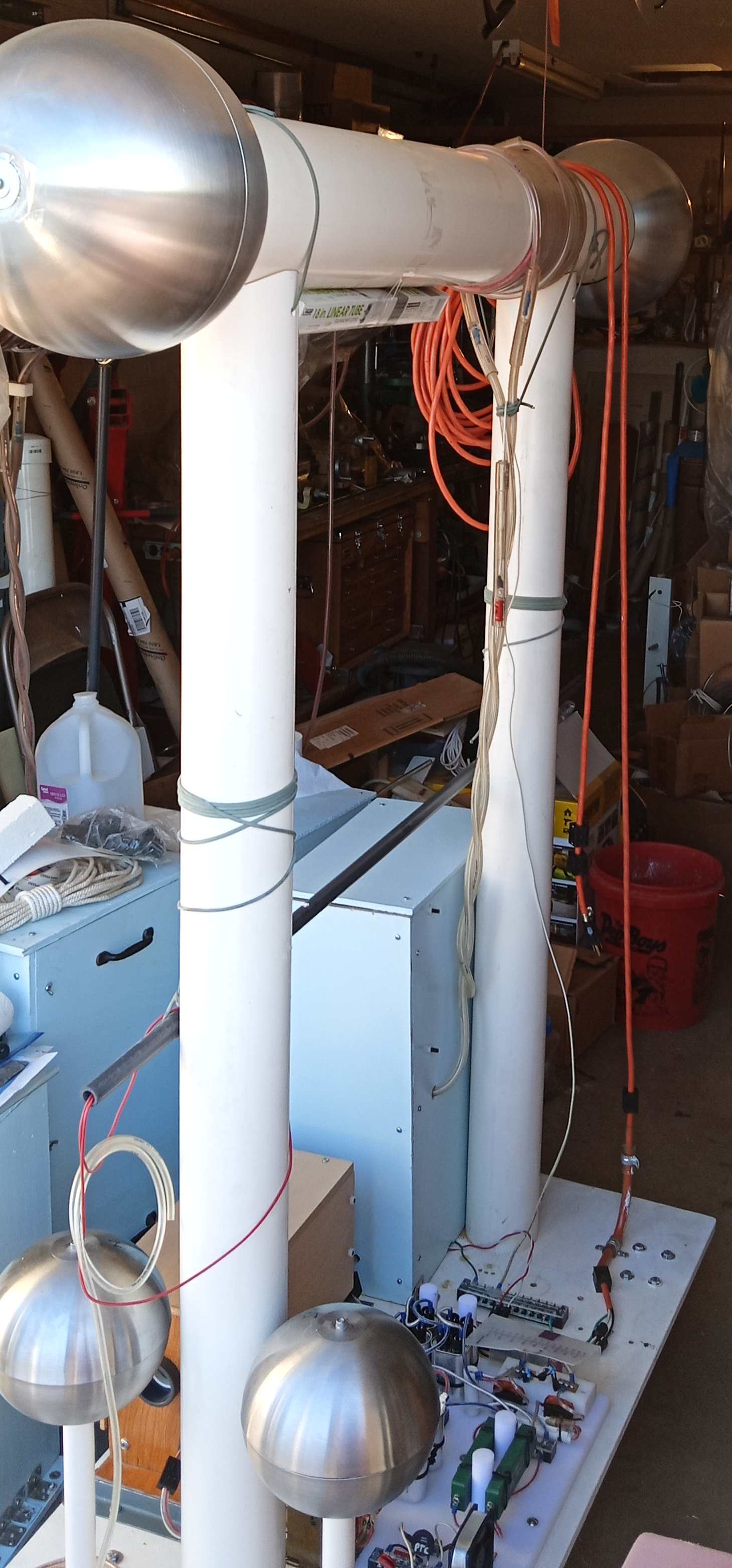
 |  |
| The coil assembly is mounted on two vertical 4" ID PVC tubes that are about 5 feet long, which are in turn mounted on a plywood base plate with casters. Base studs go inside the tubes to hold them in a vertical position. They are made from 5 plies of 3/4" MDF (Medium Density Fiber board). | Bolt holes have to be bored into the studs so they can be mounted on the 3/4" plywood base. Bolts are made from 1/2" x 7.5" threaded rod. They also go through the U channel stiffener that runs the length of the 2' x 4' plywood base. |
 | |
| This shows the underside of the 2' x 4' x 3/4" plywood base board with the U channel stiffener, the casters, and the base studs (which will be mounted on the other side). |
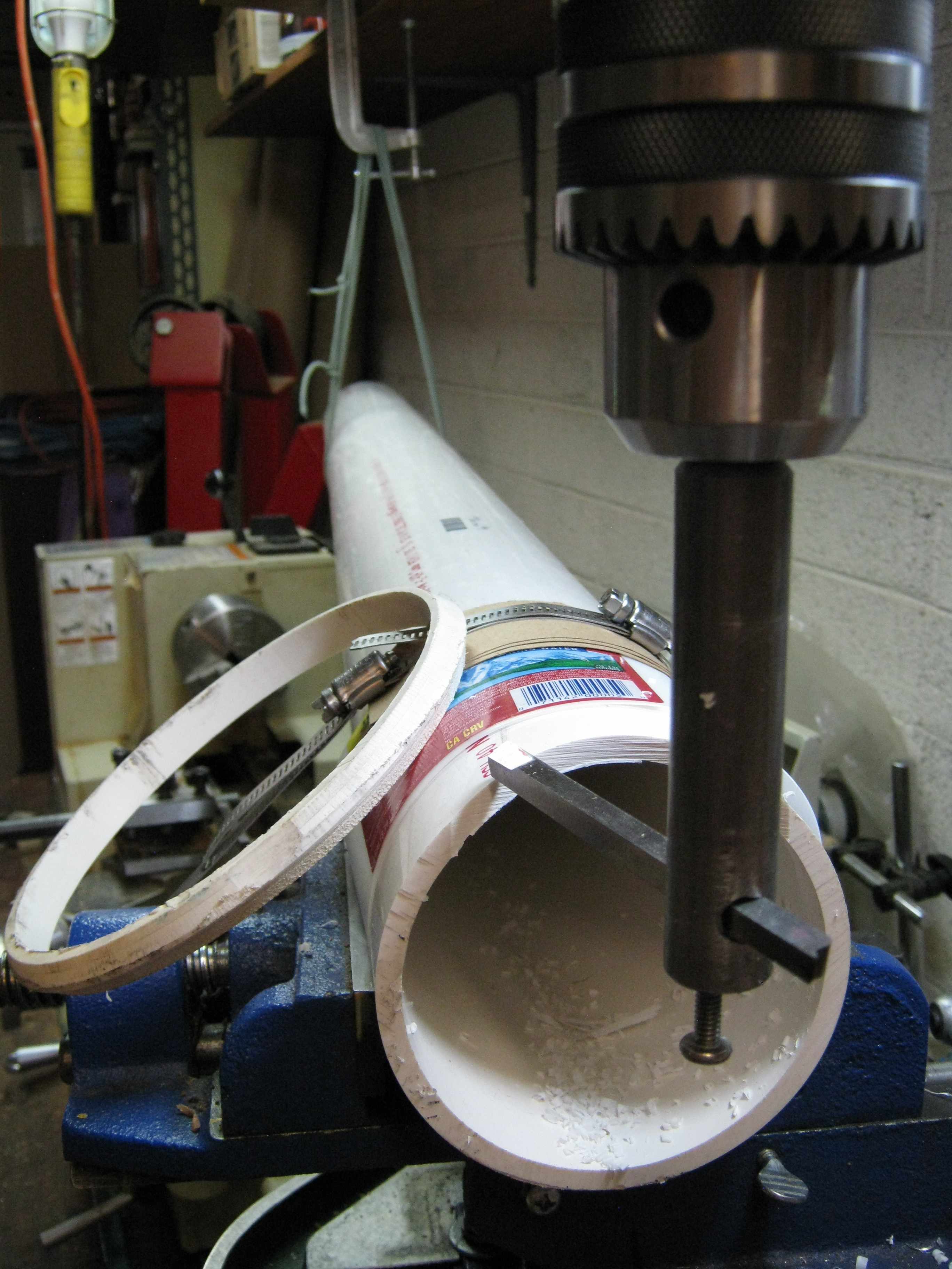 | 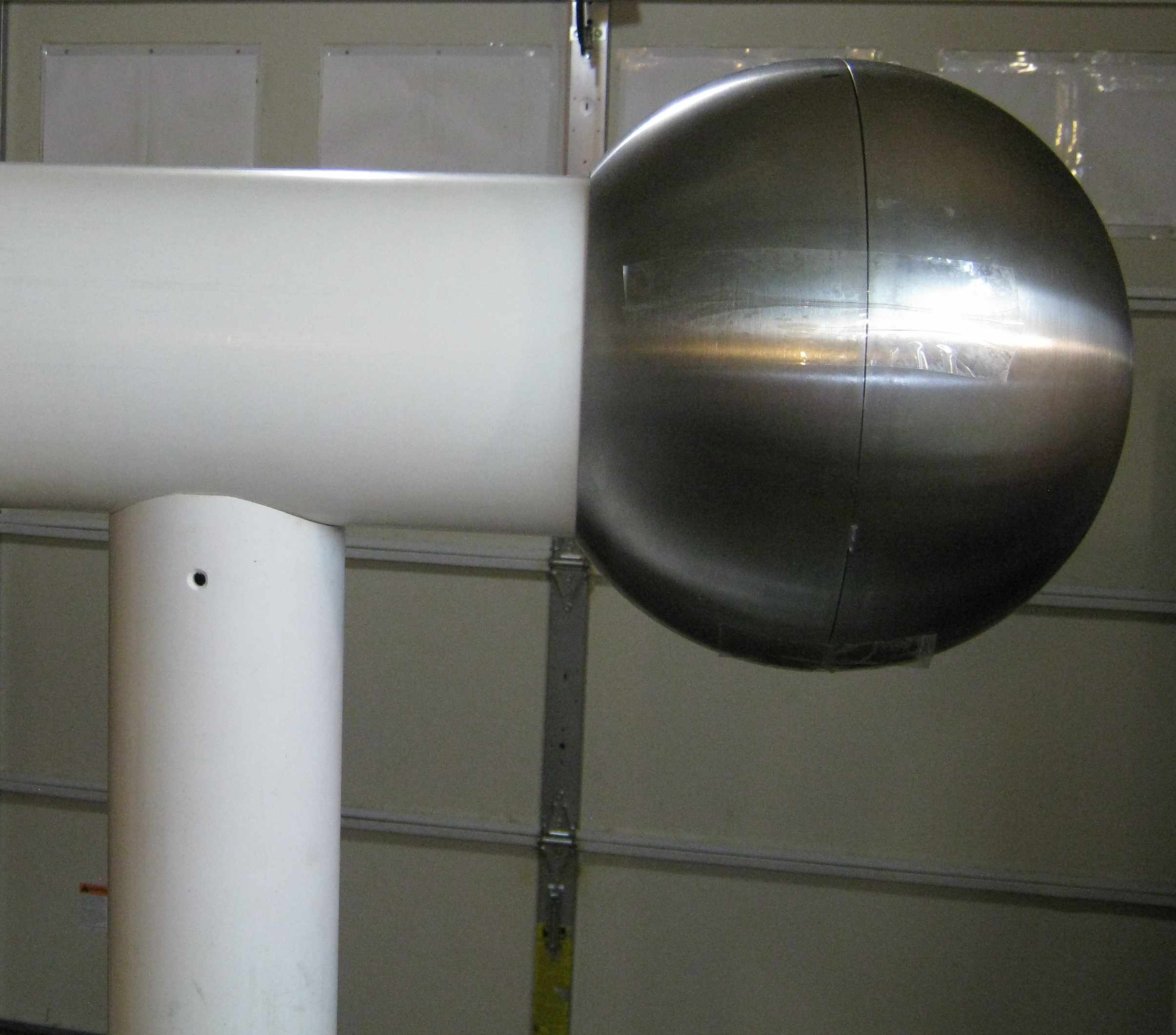 |
| A
fly cutter (homemade) is used to cut a contour on the end of a 4.5" OD
vertical PVC tube to mate smoothly with the 6.625" OD horizontal
tube (which serves as a cover for the Tesla secondary winding and a
surface for the Tesla primary winding). A ring previously
trimmed from the 6.625 OD tube is used to check the profile. Note how the far end of the tube is held up by a loop of parachute cord, and the near end is held in an undersized vise by hose clamps. | This
is a picture of a vertical support tube and one of the end spheres.. The tubes slip over the base
studs which are bolted to the plywood base. The horizontal coil housing
rests on top of the two tubes. The hole at the top of the vertical tube is for a parachute cord tie-down of the horizontal tube which contains the secondary winding). For storage, the spheres are removed and the vertical supports are removed from the base. Everything else easily disassembles. For experiments the Tesla primary and secondary coils can be lifted off the supports and moved to the test station. The primary is reconnected to the power supply by a long twisted pair "extension cord" that can handle 15kV safely. |
| Cutting
the vertical tube profiles is tricky. The tube is rested between
the jaws of an x-y vise on one end and the other end is hung from
parachute cord to make an overall level tube. The machinable end of the
tube is secured with a long hose clamp threaded thru openings in the
x-y vise. Tool length must be set to 3.312” from centerline of holder. Center line of holder must be parallel to the vertical centerline of the tube cross-section. Tool must be very firmly anchored in holder and checked periodically for looseness. Only very thin, shallow cuts should be made. Periodic checks of alignment must be done with an 8”carpenter’s adjustable square/ruler: The profile is first cut only halfway down the endface of the tube. Then the drill press is turned off and the cutter is lowered to about midway down face of the tube. Then the spindle is locked in (vertical) position. Two marks are placed on the tube edge on either side across from each other (rotate the spindle to locate the marks precisely). Then loosen the hose clamp on tube and rotate the tube 180 degrees. Bottom now becomes top. Get the alignment correct by using the marks (may have to change spindle height). Retighten the hose clamp. Proceed to cut the remaining half of the end profile. Now evaluate the accuracy of the cuts: Loosen the hose clamp and slide the tube about 8” out from the vise. Place the frame of the carpenter’s square along the long axis of the tube. Extend the ruler across the diameter of the tube at the cut end and flush with one “peak” (at the sides). The other end of the ruler should be flush with the other peak. Repeat for the valleys (on top and bottom). If the two valleys are not flush (cut to equal depths), then the tube is not perpendicular to the rotation axis of the cutter. Adjust the far end of the tube up or down as required and then recut to remove excess; only one half of the tube face should be affected. Recheck with the carpenter’s square. Note: only one half of the tube face is cut at a time. This is to avoid problems with lack of rigidity due to a long extension of the fly-cutter. The top-down motion on the upper half also simplifies grinding of the cutting tool because the bottom of the tool will not be cutting any plastic. | |
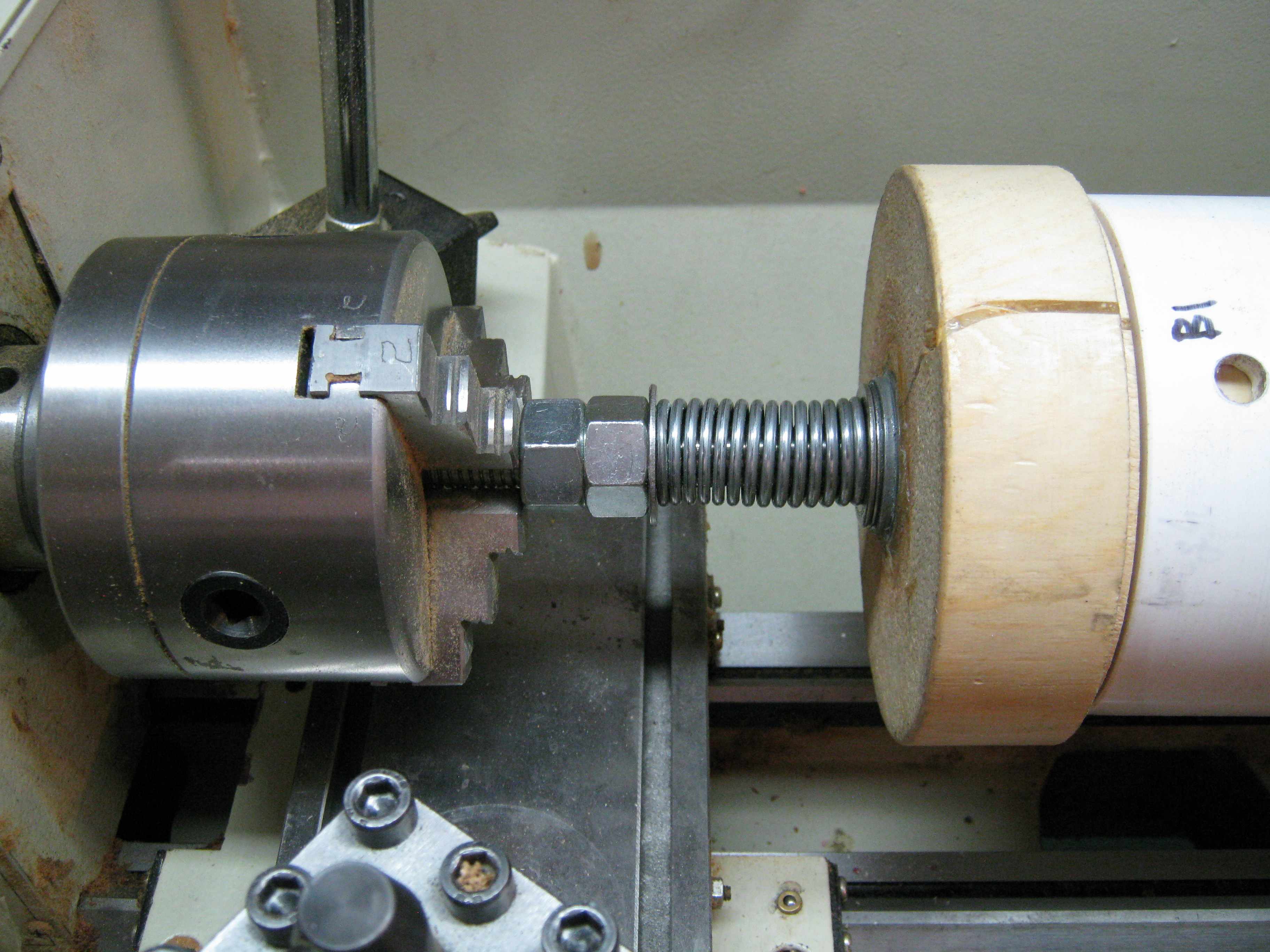 |  |
| About 2000 feet of #24 AWG copper magnet wire has to be wound on the 4.5" OD tube. Doing this entirely by hand would be tedious and time consuming. Hence, an arrangement was made to drive the tube from a lathe chuck by using a slip clutch made from a spring and some washers. The lathe is run with reverse rotation and at its lowest speed. | Turns
are kept adjacent and tight with fingernails and finger pressure. The
wire is tensioned by letting it slide between folds of paper towel that are pinched together by the other hand (not shown).
After about 4 inches of turns are laid, the lathe is stopped and the
turns are sprayed with clear acrylic lacquer to anchor them in place. The coil winding took about a half-hour and was by far the easiest of all the fabrication operations . |
 |
| This
is the finished Tesla secondary coil. Its 52 ohm resistance is
equivalent to about 2000 feet of wire. Two MDF centering rings
protect the coil when it is slid into the outer 6" tube. Note the improvised tailstock at the far right. |
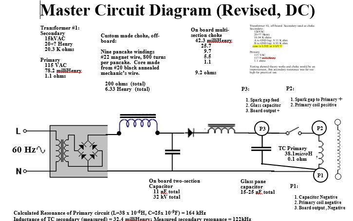
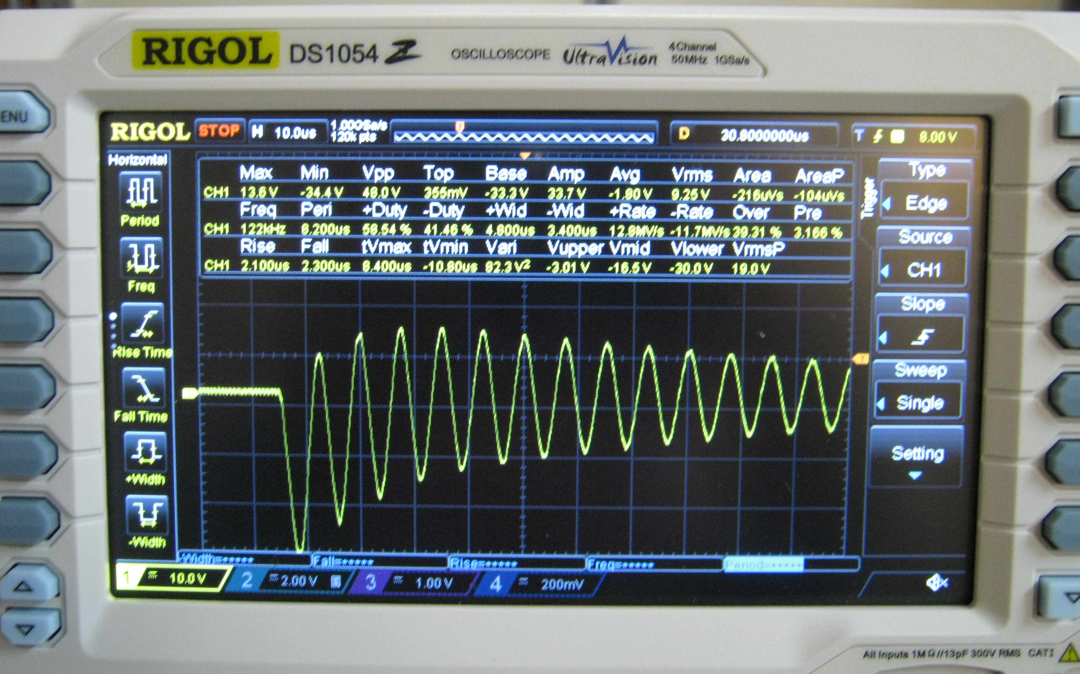 | This is a 'scope trace showing the self-resonant frequency of the Tesla secondary
with both end spheres attached. The primary consisted of 5 turns of #16
wire and was "pinged" with 1.6 volts from a small battery. The result
captured on the single sweep display was: Freq = 122kHZ Vpp = 48 volts The turns ratio in this test is therefore about 48*5/1.6 or 1:150 Text book calculations for inductance, capacitance, and resonance were: L = 12.6*(10^-7)*(1)*(2000^2)*(0.003806)/(0.8636) (MS Word field formula) =22 millihenry (measurement with a Proster LCR BM4070 meter gave 33 mH) C for two partial 14" spheres = 20 picofarads (est.) The distributed capacitance of the coil was not included. freq = (10^6)/(6.28*(22000*20)^0.5) = 240 kiloHertz |
 |  |
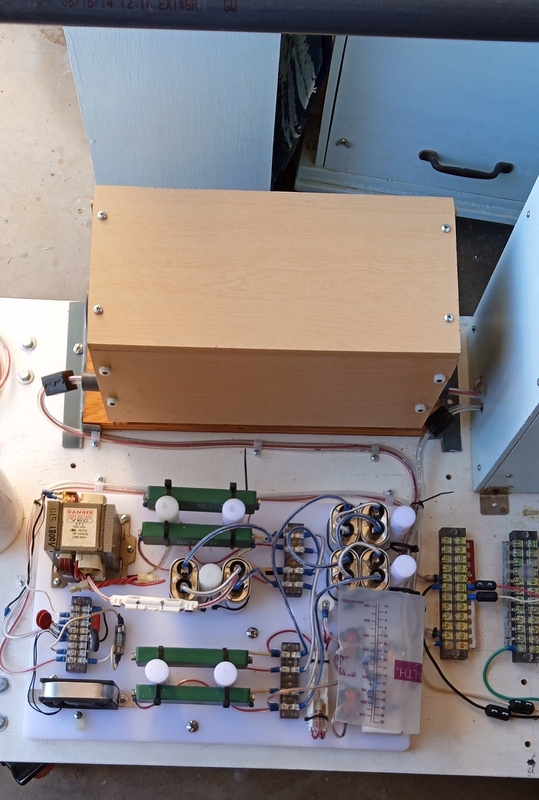
| This is the air cooled sparkgap switch assembly mounted on 1/4 -20 x 4" "stilts". Two Stainless steel carriage bolts serve as electrodes. The heat sinks are brass and aluminum. The magnetic gap consists of two 1.5" x 1.5" x 0.5" neodymium N42 magnets mounted on a heavy steel frame (supported by a leg and grounded to the transformer). The magnetic gap is intended to quench the spark for reverse polarity ringing. Its effectiveness has not been evaluated. The "keeper" for the magnetic circuit is shown resting on the blue wooden base | This
is the same switch mounted in a noise containment box. The fiberglass
batts (yellow) help to absorb high-frequency sound from
the spark gap. The panel on the right is held in place during operation by 8-32 studs and knurled fingernuts. The glass shields around the spark gap are visible. |
 |  |
| .This is how the glass pane capacitor is made. It starts with a 16" x 20" glass window pane being overlaid with 12" heavy duty aluminum foil. The foil is later trimmed to give a 2" foil free zone around the glass. Then the corners of the foil are rounded. Then all the edges are covered with packaging tape to reduce corona. Finally, the electrode wires are attached. All the steps are detailed in GlassCapacitorConstruction.docx . | Finished glass capacitor pane with male bullet connectors. Four plates connected in parallel gave a capacitance reading of 14.75 nanoFaradson a Proster LCR BM4070 meter |
 | |
| This photo shows the female bullet connectors that will connect the glass pane capacitors (not shown) to the system. Note the two figure 8 knots that prevent the wires from being inadvertently pulled out. The PVC tubes can be lifted out for insertion of the capicitor panes. |
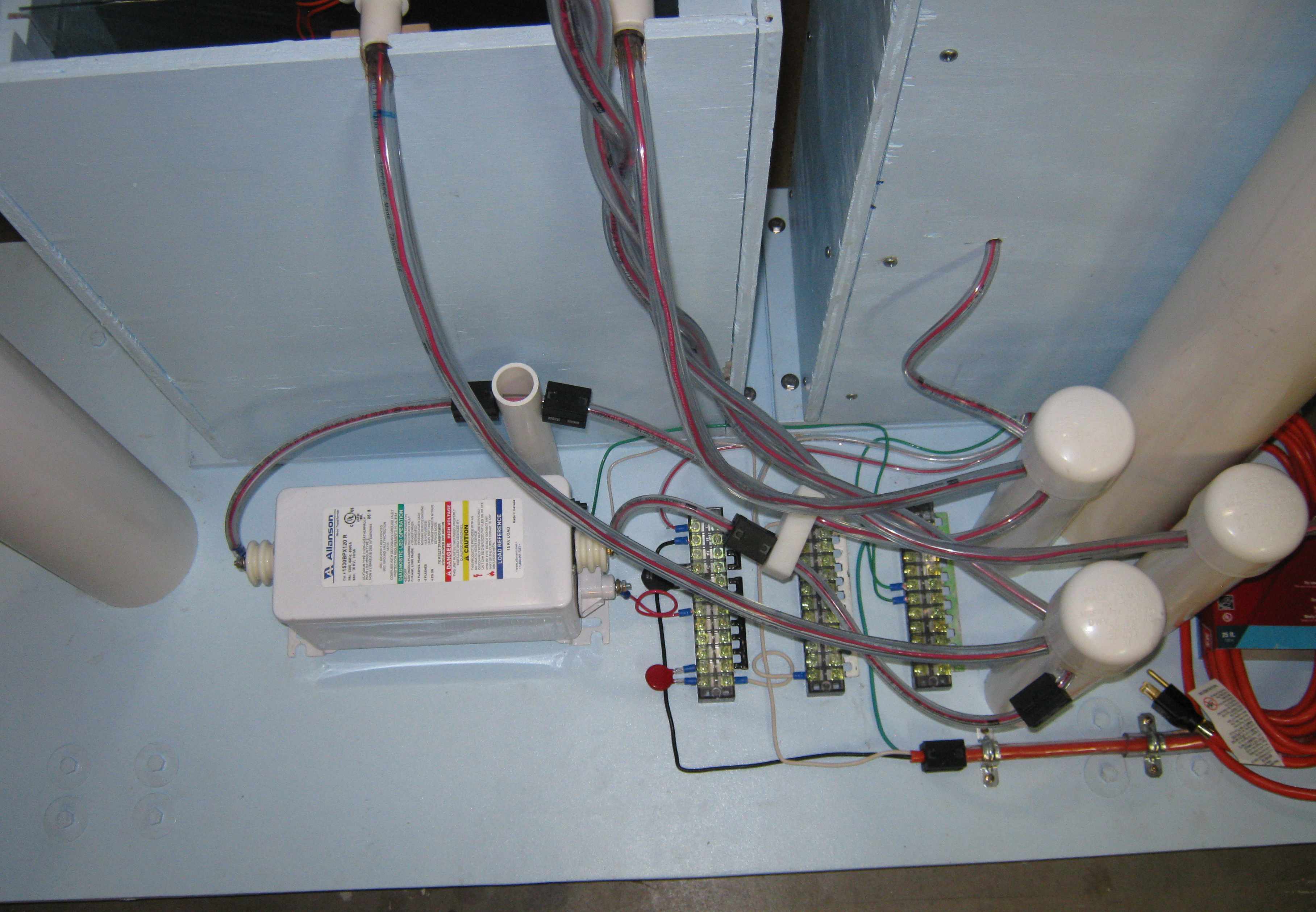 |  |
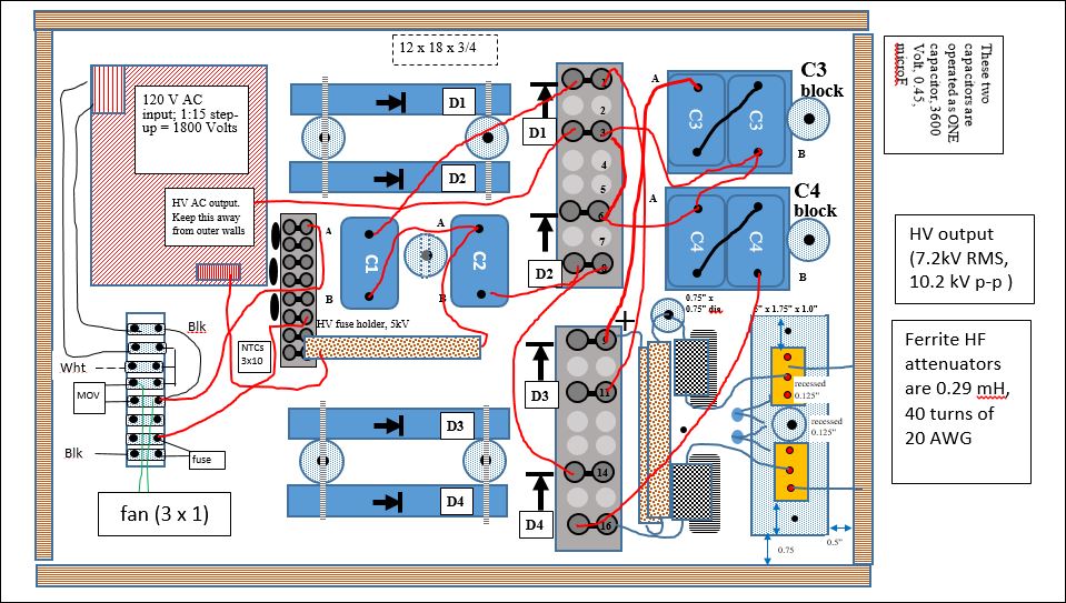
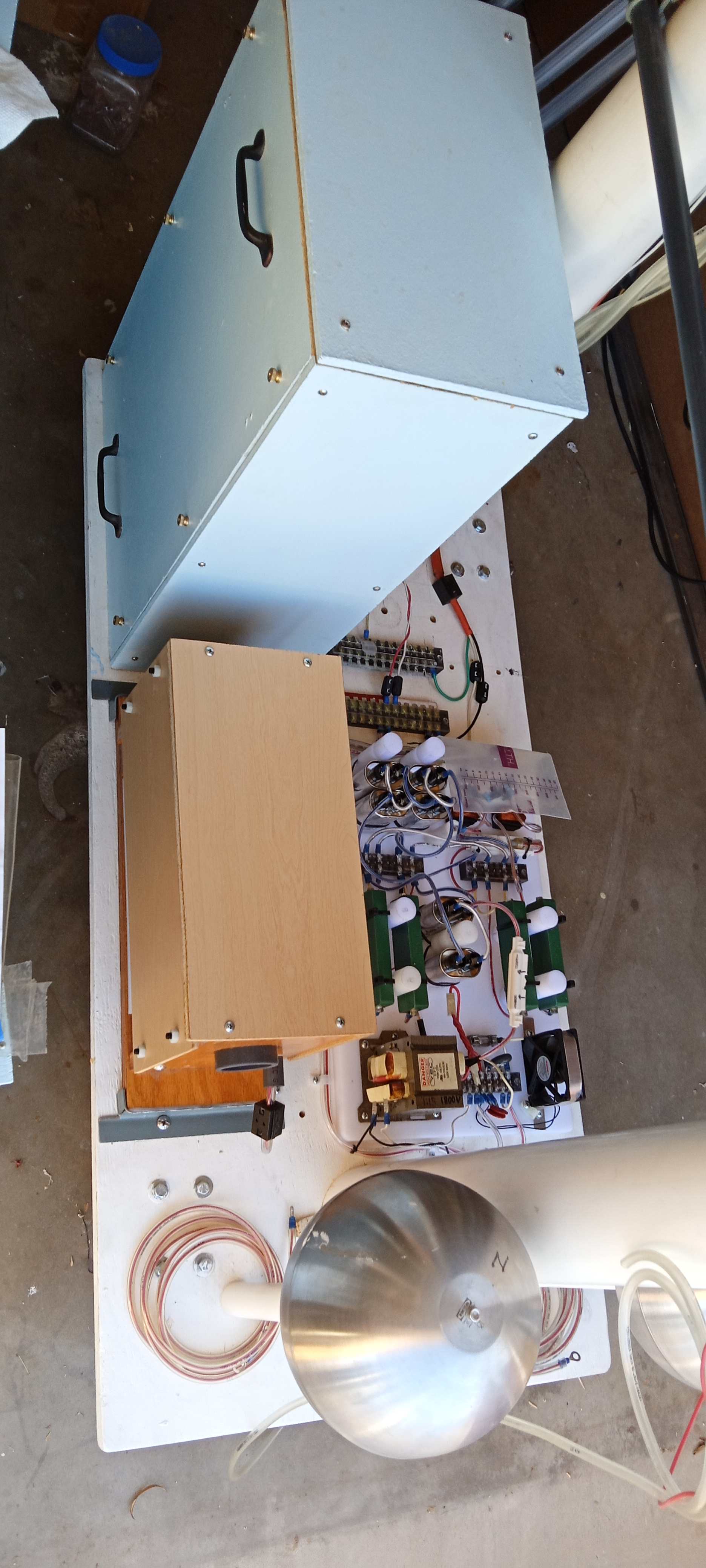
| This
photo shows the wiring for the 15kV part of a very basic Tesla coil.
The original design was for a DC coil, but the rectifier board failed
to deliver sufficient current output. And so the final implementation was just
a run-of-the-mill, ordinary bipolar AC Tesla coil. See below for a discussion. The black cube-like items are EMI filters intended to prevent high frequency oscillations from damaging the neon transformer.The PTC soft-start and overvoltage protection MOV are visible on the left terminal strip. The GFI inside the transformer did not present any problems. | This is what the inside of a terminal post looks like. It is simply a safe place to make high voltage (15kV) connections. The extra insulation enveloping the wires is made from two different diameters of clear vinyl tubing. The smaller is pulled through the larger to give a thicker wall. |
 |  |
| The
operation of this setup was somewhat noisy. I at first thought the
acoustic containments for the spark gaps were inadequate, but it turned
out the noise was coming from the high-tension wires going into the
test tower. I sheathed all four of them with vinyl tubing and the noise
was reduced considerably. High frequency corona from the wires is visible at night and will go thru intact insulation to a nearby object (including my head!). | This is another view of the setup. The initial shakedown test was successful (no blown fuses, complaints from neighbors, etc.) |


 |  |
 |  |
 |  |
| mount with 3M spray adhesive. the outer circle first then cut inner circle | finishing bobbin disk |
 | |
| bending bobbin cylinder 325 F |
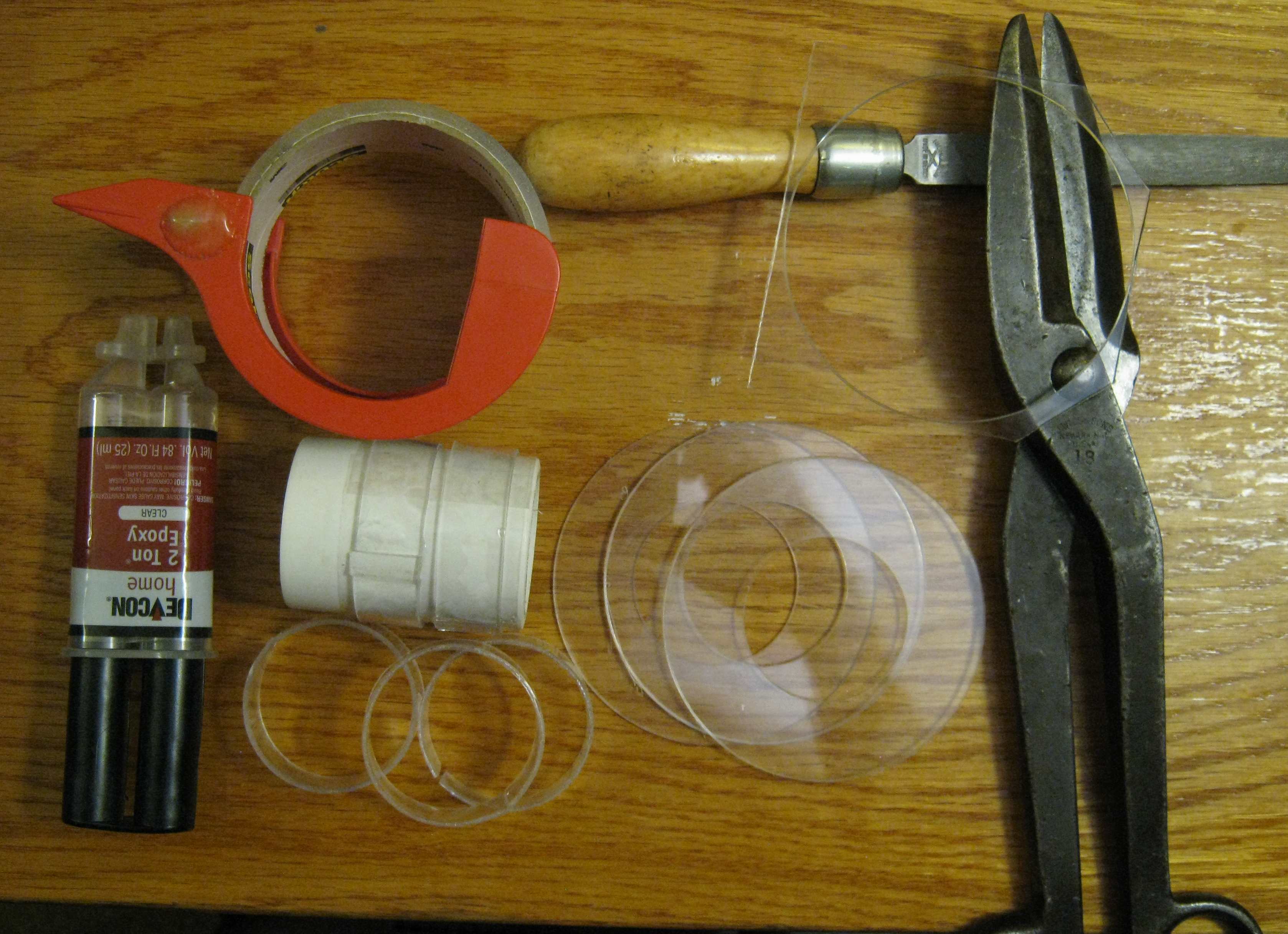 | |
| inserting cylinder fillet on mandrel | finished bobbin |
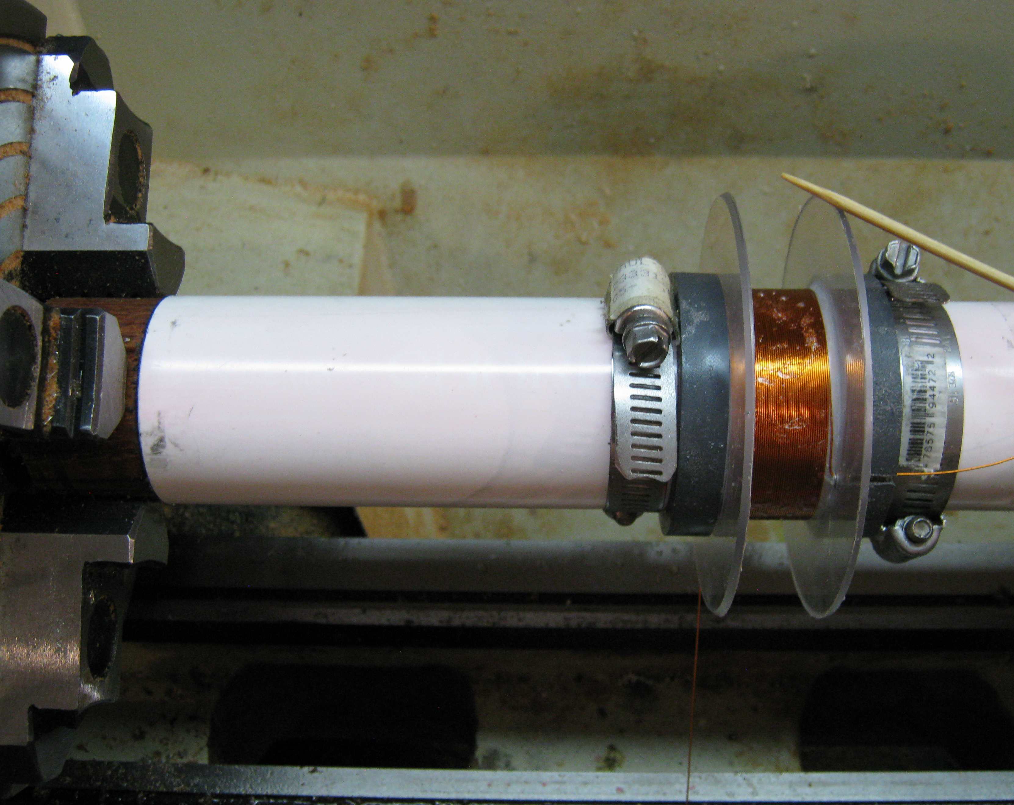 | |
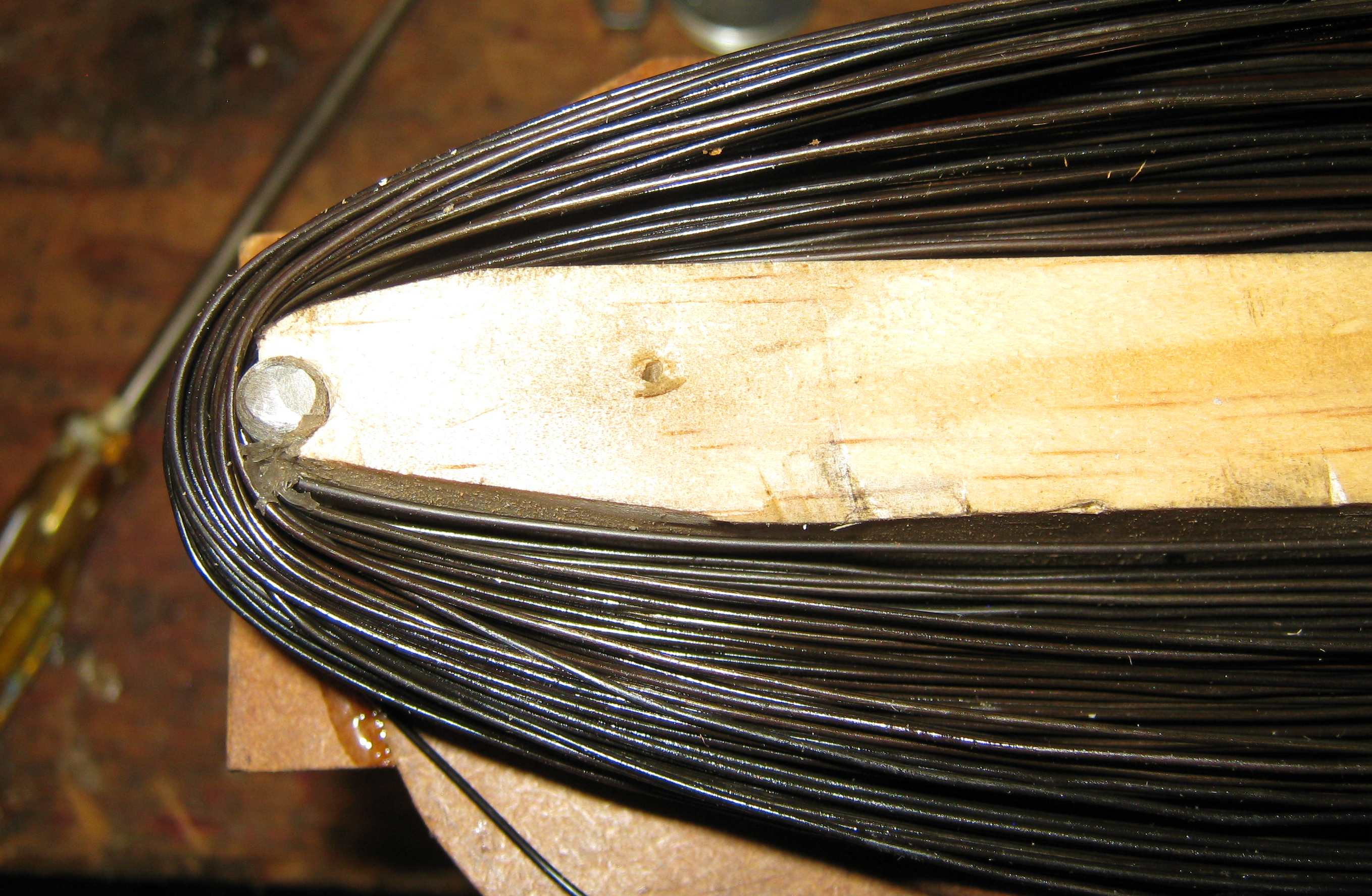
| cutting coil spacers | winding a pancake coil 3M spray adhesive is used to anchor the turns spacers and hose clamps keep the bobbin in compression and from splitting apart as the wire is added. |
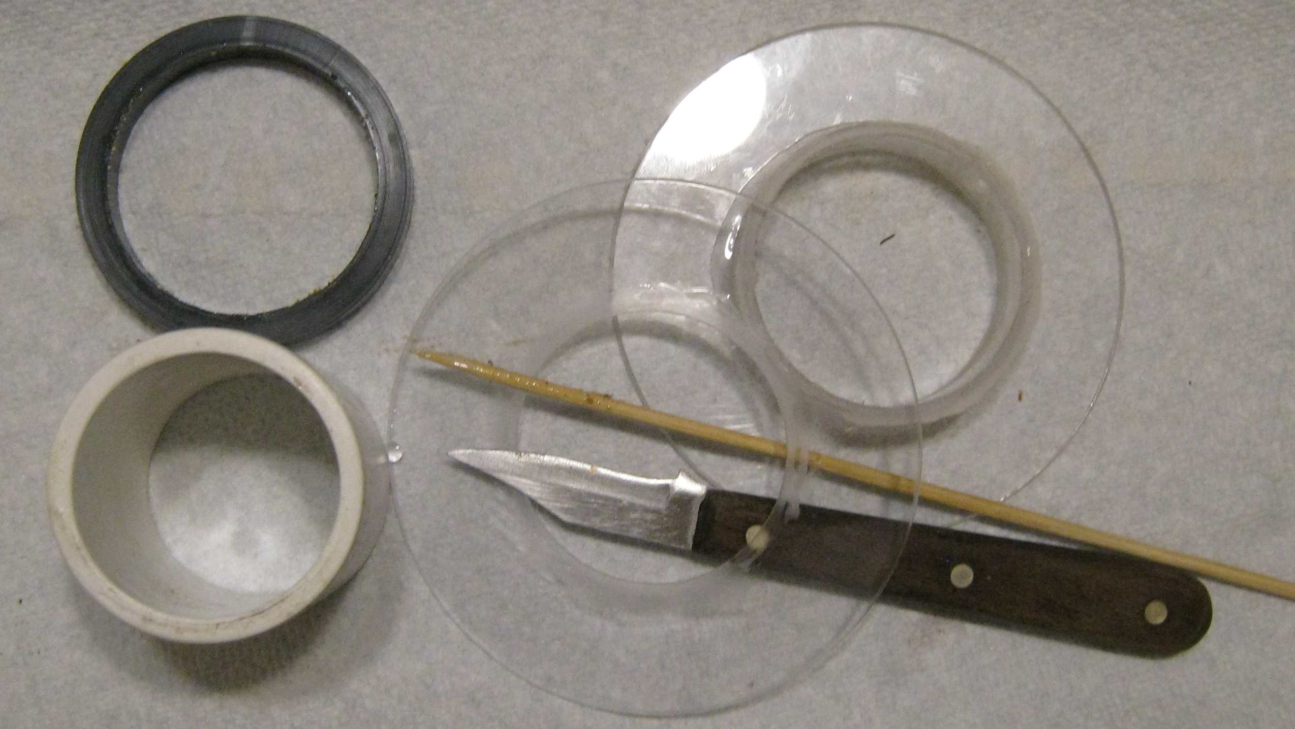 | |
| repair of damaged bobbin two bobbins split assembly is not weak but not robust either. | |
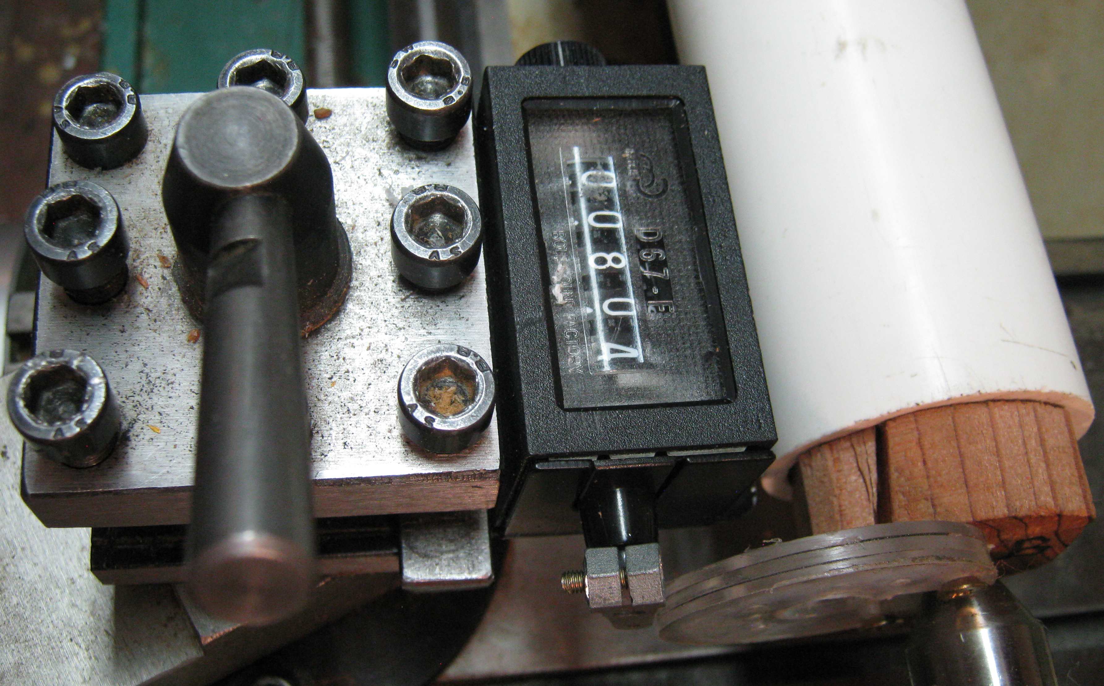 | 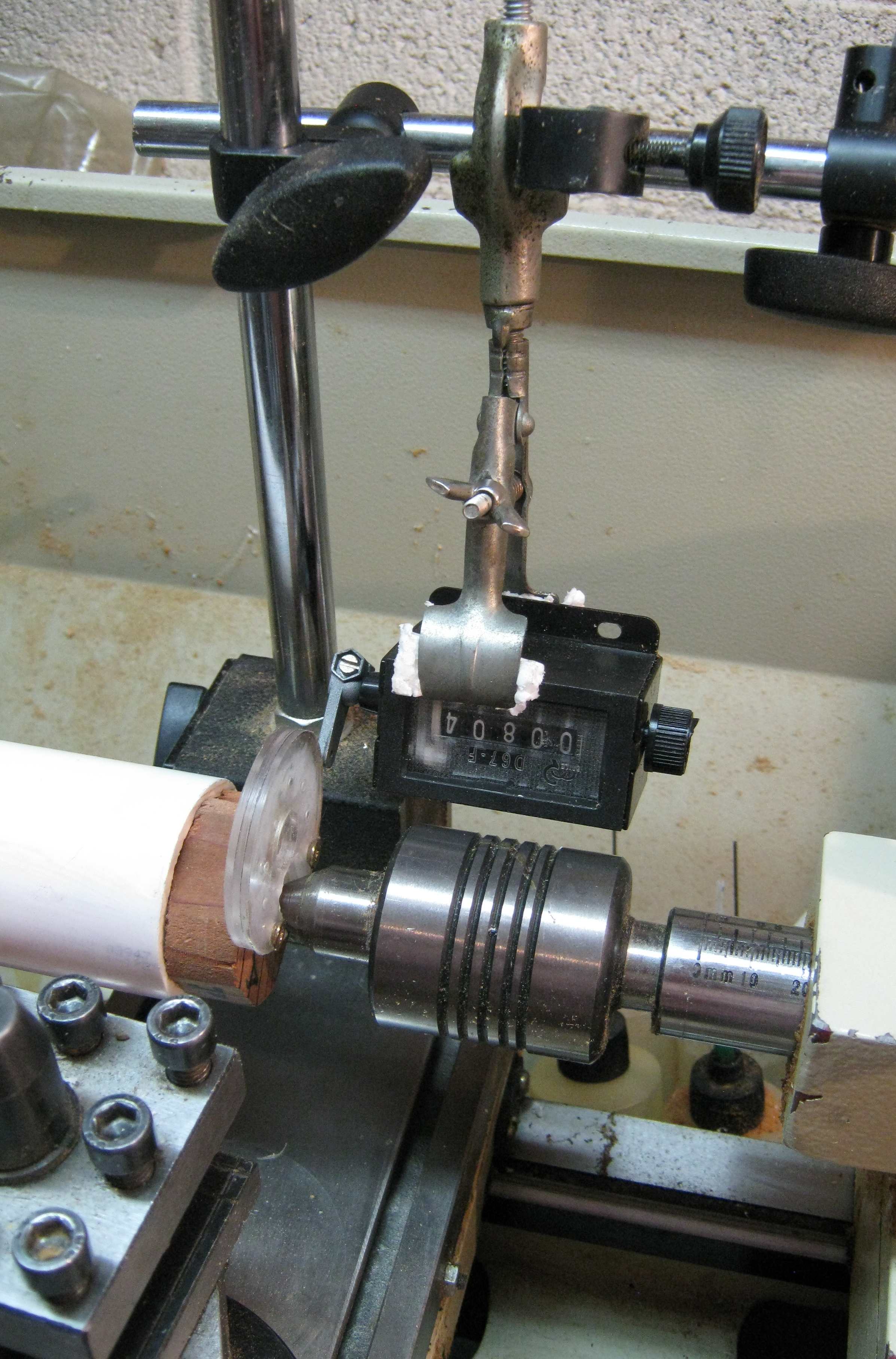 |
| CCW counter | CW counter |
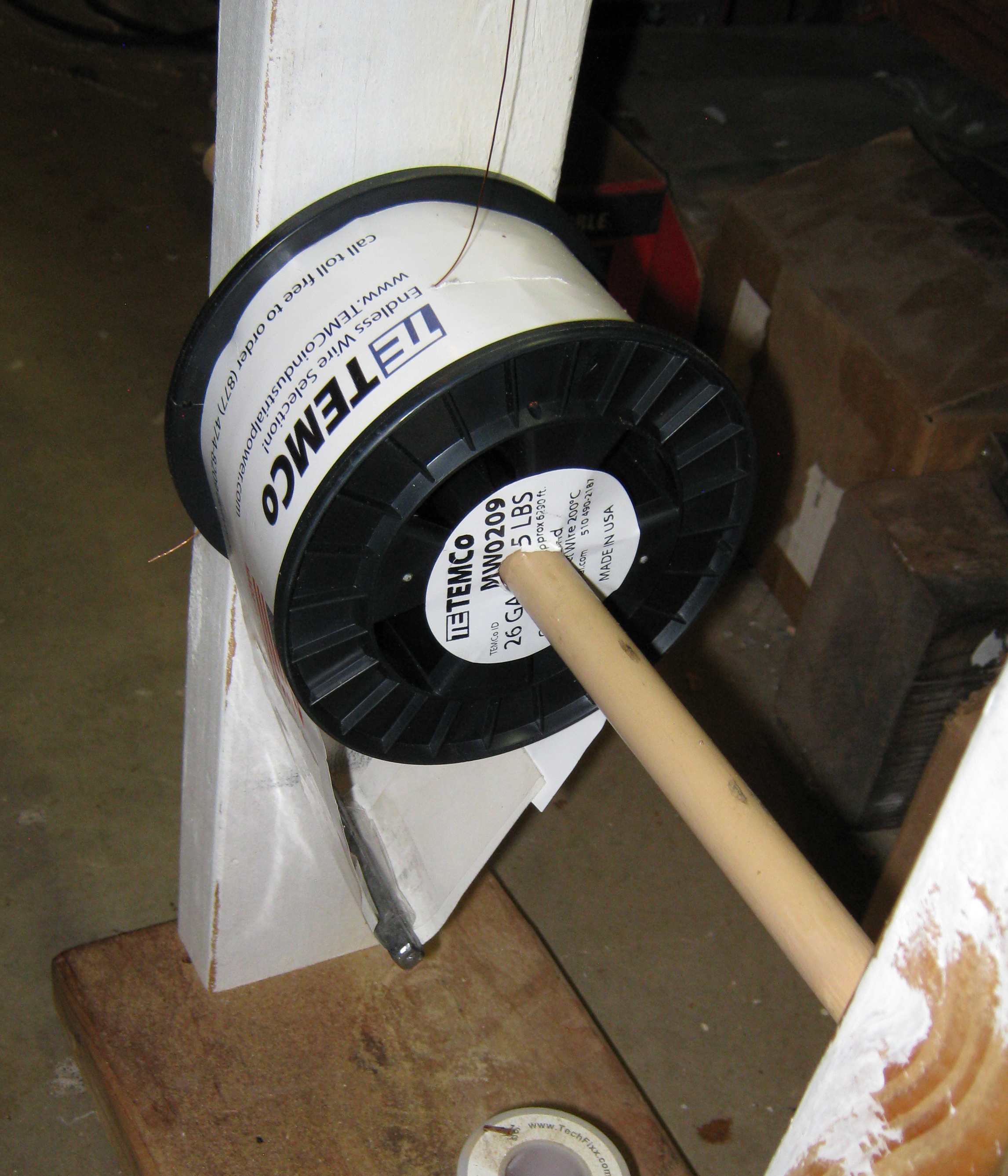 | |
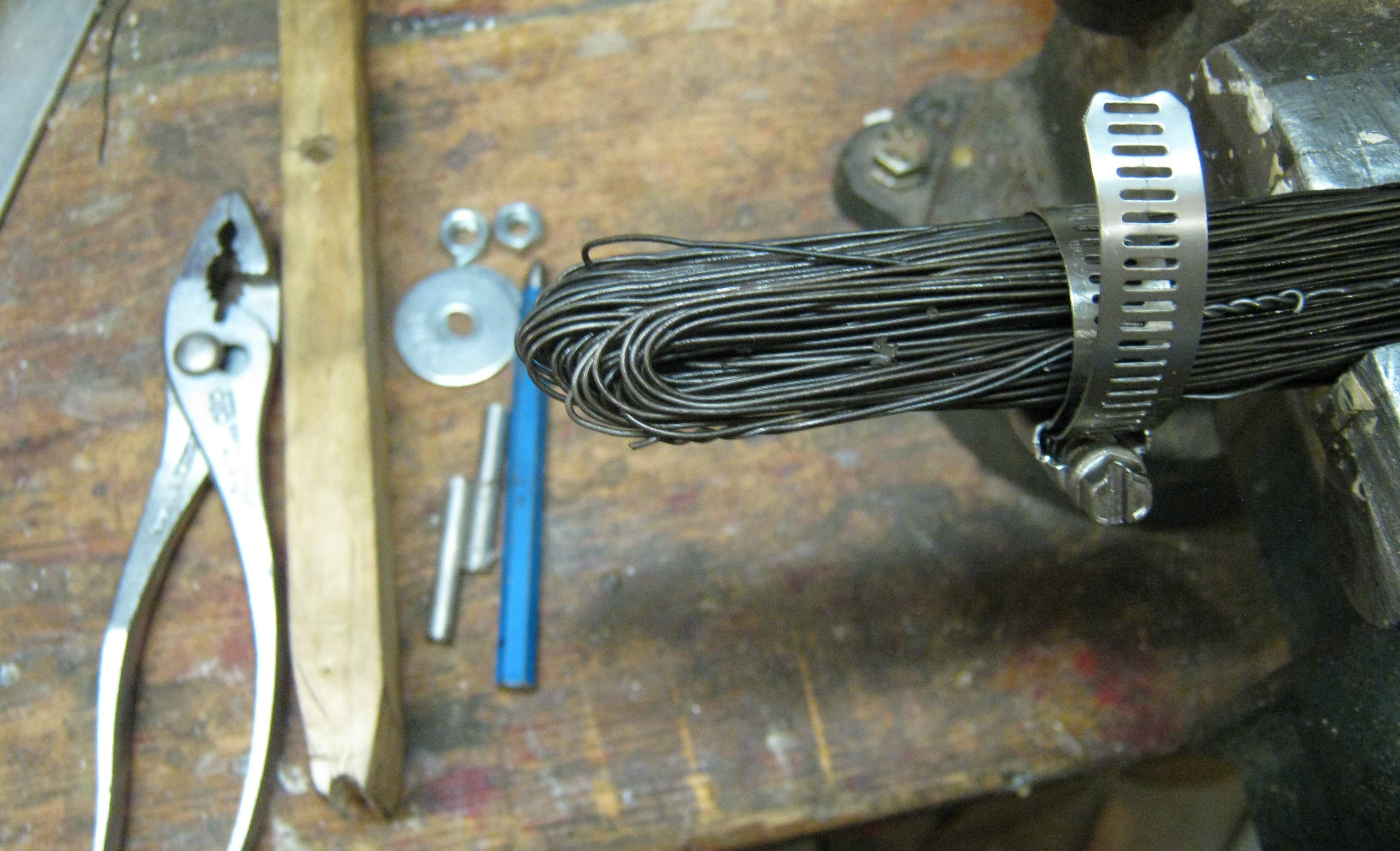
| constraining wire to spool |
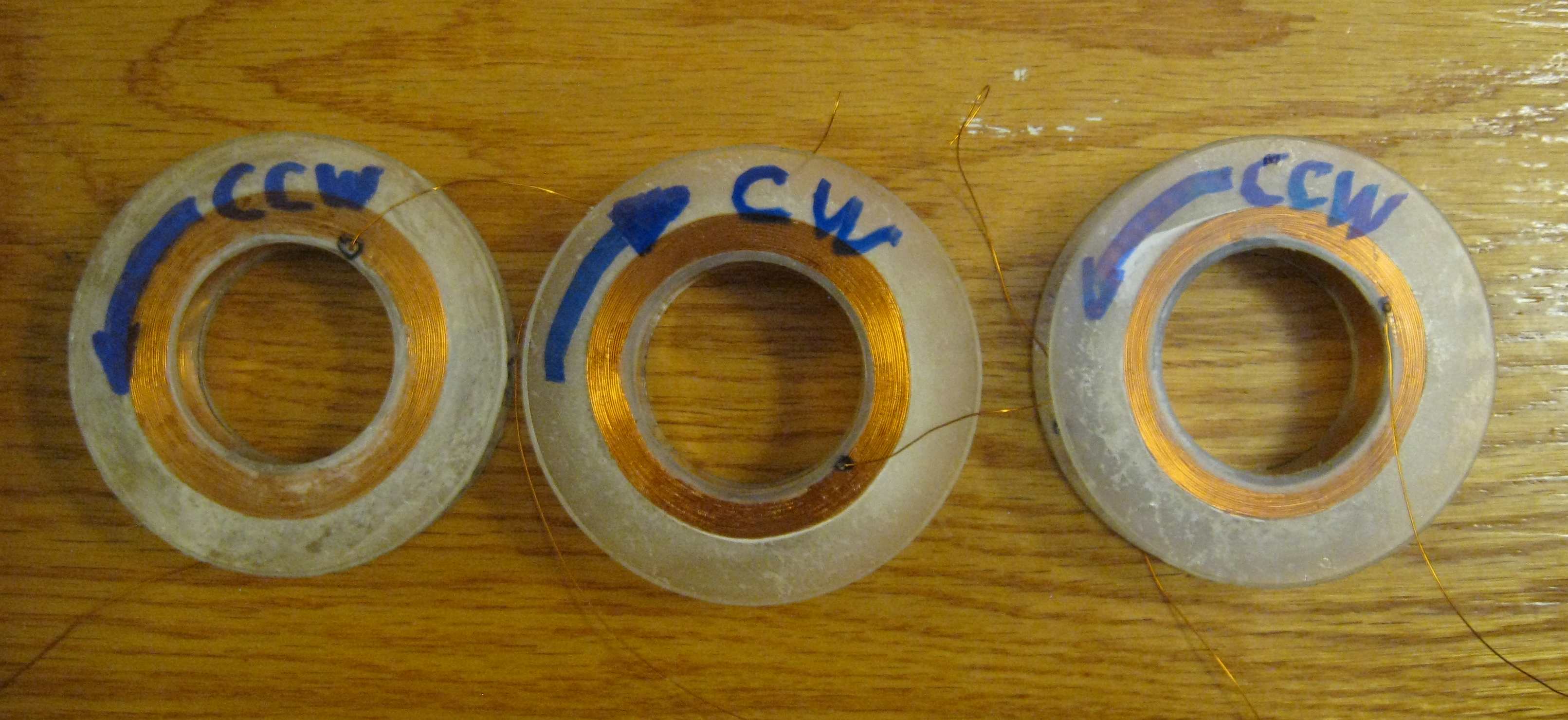 |
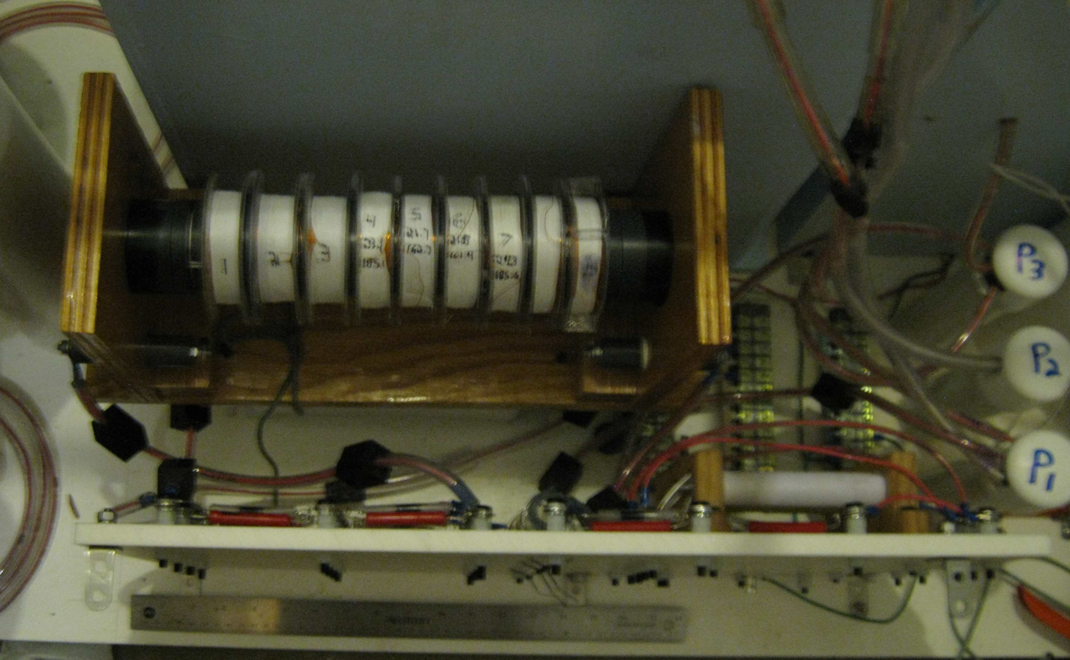
| final coils. See ref: |
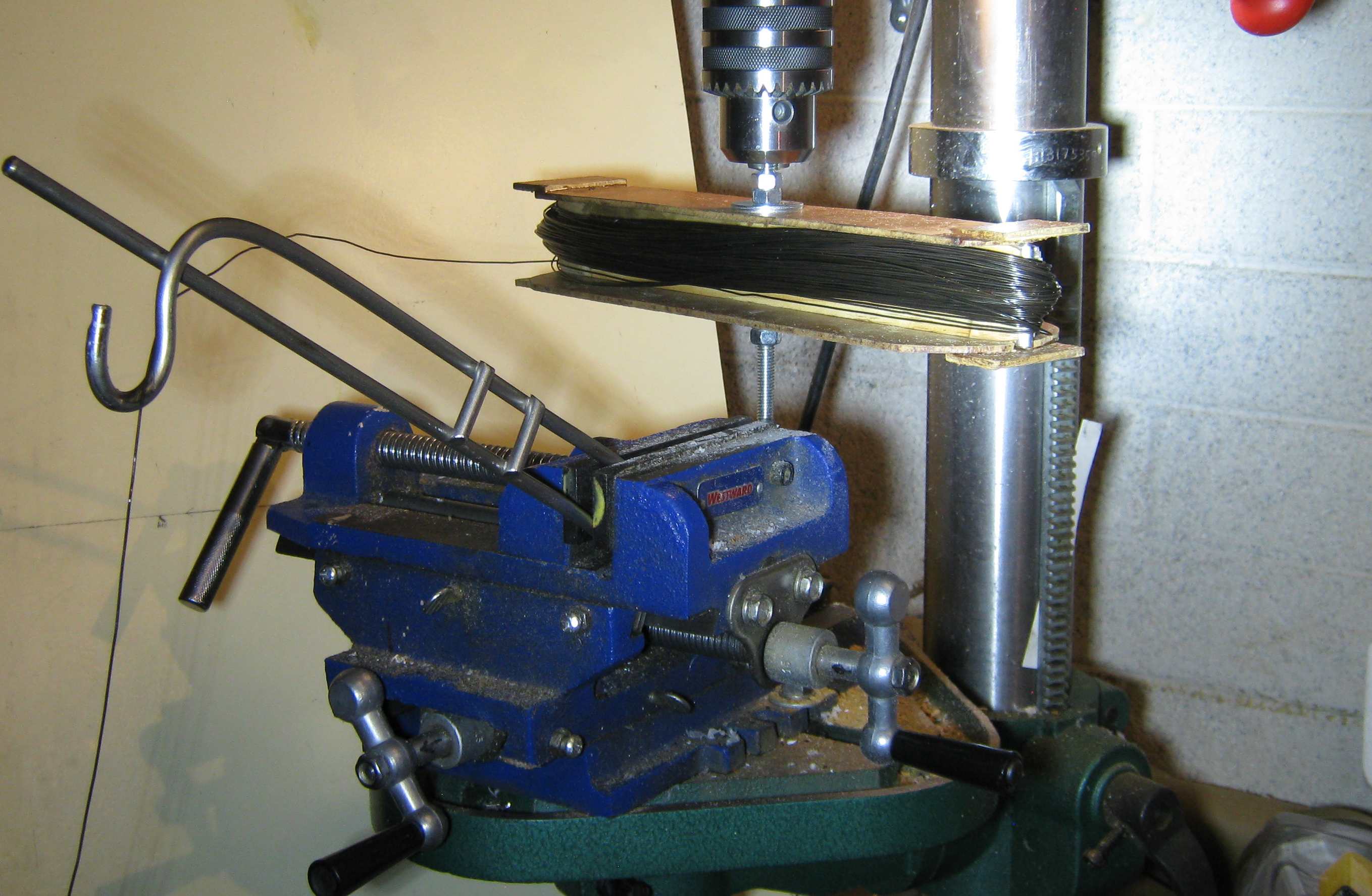 |  |
| could not find transformer steel in small quantities must be duplicateable used #20 annealed black iron wire various cleaning attempts sprayed with acrylate | |
 | |
 |
 |  |
 |  |